13
GENERAL SPECIFICATIONS
MVP Panel
RESET
GEN
LOCK
EXT
INT
NTSC
RGB
FILTER
ON
OFF
VBS
Y/C
MODE
RATE
RS-232C
VD
H/C SYNC
R
B
G VBS Y
C
INPUT OUTPUT
VOUT1 VOUT3
VOUT2 VOUT4
VBS/G
Y/B
C/R
VBS/G
Y/B
C/R
VBS/G
Y/B
C/R
VBS/G
Y/B
C/R
ON
OFF
POWER
=
2
3
~
!
@
1
5
7
8
9
4
6
0
-
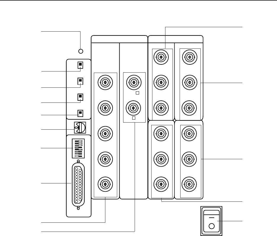
1 POWER switch (Power)
Used to turn on/off the MVP power.
2 Reset button
System reset button. When this switch is
pressed, the system sets into the manual mode
and operates in the modes of the switches set
on the panel.
3 EXT/INT switch
Normally, this is set to the INT side so that the
MVP operates in the free-run mode for video in-
puts.
Leave it at the INT side unless when using the
MVP for special uses such as locking the MVP to
the video input.
4 NTSC/RGB switch
Select whether to set the NTSC input or RGB in-
put to 4-screen magnification.
It is set to the NTSC side at shipment.
* When switching the switch, press the reset
button after switching.
* The RGB input is an option.
5 RGB input vertical filter on/off switch
Vertical filter on/off switch of optional RGB in-
puts. If the top and bottom of the RGB input im-
age do not fit inside the output screen, turn on
this switch.
At shipment, it is set to off.
6 VIDEO/YC switch
Switch to set whether to input VIDEO or YC into


