


14
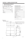
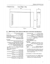
GENERAL SPECIFICATIONS
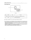
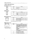
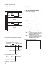
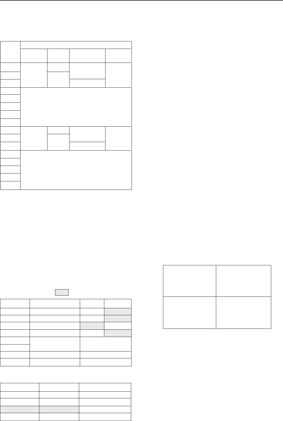
7 MODE switch
Used to select the video output mode.
Output Mode Switch Contents
Output Mode
*2
RGB
OFF
RGB
ON
RESERVED
RESERVED
Switch
No.
0
1
2
3
4
5
6
7
8
9
A
B
C
D
E
F
NTSC
NTSC
Frequency
Mode
Output
Mode
VBS,Y/C
VBS,Y/C
Standard Speed/
Double Speed
*1
Standard Speed
Double Speed
Standard Speed
Double Speed
*1
Standard speed horizontal frequency 15.734 kHz
Double speed horizontal frequency 31.468 kHz
*2
The switch is set to 8 at shipment.
Normally, use in the range from 8 to A.
Press the reset button when switching the mode.
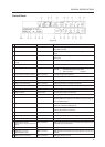
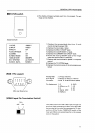
8 Baud rate switch
Used to select the RS-232C (For controlling
MVP) baud rate.
Baud rate selection switch (8 BIT DIP)
Functions of bit ........ Value at shipment
Switch function ON OFF
Parity yes/no Yes No
Parity polarity EVEN ODD
Character bit 8 BIT 7BIT
Stop bit 2BIT 1BIT
Baud rate setting See table below
RESERVED
RESERVED
Switch No.
1
2
3
4
5
6
7
8
Always use at off.
Always use at on.
Baud rate set by switches No. 5 and 6.
SW1 -5 SW1 -6 Baud rate (bps)
ON ON 19200
OFF ON 9600
ON OFF 4800
OFF OFF 2400
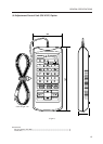
9 RS-232C connector
For controlling MVP
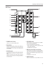
0 RGB video input terminal (Optional)
Optional RGB input terminal.
G .....................G signal input terminal of RGB
separation signal
B ..................... B signal input terminal of RGB
separation signal
R ..................... R signal input terminal of RGB
separation signal
H/C SYNC ...... H sync or C SYNC input terminal
V ..................... V sync input terminal
- NTSC video input terminal
NTSC input terminal
VBS .. Y signal input terminal of composite
video or Y/C separation signal
C ....... C input terminal of Y/C separation signal
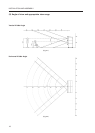
= to @ Video output terminals 1 to 4
4-screen magnification video output.
VBS/G .... G signal input terminal of composite
video or RGB separation signal (Out-
puts G on SYNC during G signal out-
put).
Y/B ..........Y signal output terminal of Y/C sepa-
ration signal or B signal output termi-
nal of RGB separation signal.
C/R ..........C signal output terminal of Y/C sepa-
ration signal or R signal output termi-
nal of RGB separation signal.
The signals correspond as follows.
* At shipment, 3, 5, and 8 are ON.
(Front View)
V OUT
Screen 1
V OUT
Screen 2
V OUT
Screen 3
V OUT
Screen 4
Trunk Piece
Mitigation Mode