


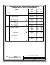
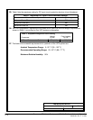
NOTE:
Callout letter and
map to drawing #164201261---3
,,,
DESCRIPTION:
DATE:
DRAWING NO:
3of11
INSTALLATION NOTES
SHEET:
REVI SION:
F
115103
164201261---1
A --- 4
Powerware BPIII Harsh Environment UPS 50--75 kV Installation and Operation
164291261 Rev. F 111503
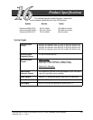
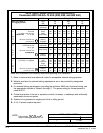
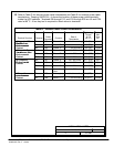
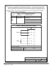
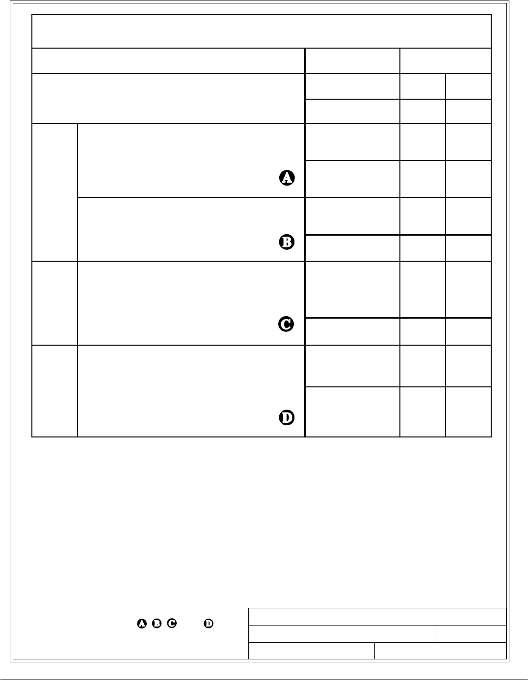
Table C. INPUT/OUTPUT Ratings & External Wiring Requirements for
Powerware BPIII HE 50 and 62.5 kVA (400 Volt)
Ratings
Units
Rating
50 Hz
Basic unit rating at
0.8 lagging PF load
KVA
KW
50
40
62.5
50
g
g
g
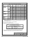
INPUT/OUTPUT
VOLTAGE
400 400
A
AC Input to UPS Rectifier
Full Load + Batt. Chg.
(.95min.PF) 3 ,(1)gnd
Amps (max) 120 140
A
C
I
N
Minimum conductor size
(number per )
AWG or
kcmil(ea)
2/0
(1)
3/0
(1)
N
P
U
T
AC Input to Bypass
Full Load Current
3 ,(1)gnd
Amps (Nom) 72 90
Minimum conductor size
(number per )
AWG or
kcmil(ea)
3
(1)
1
(1)
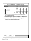
D
C
I
N
P
DC Input from Battery to UPS
(1) positive, (1) negative
VDC
Float VDC
Amps
(2.0V/cell)
120
135
360
120
135
455
P
U
T
Minimum conductor size
(number per pole)
AWG or
kcmil(ea)
3/0
(3)
250
(3)
A
C
O
AC Output to Critical Load
Full Load Current3
3 , (1) Neutral, (1) gnd
Amps (Nom) 72 90
O
U
T
P
U
T
Minimum conductor size
(number per )
AWG or
kcmil(ea)
3
(1)
1
(1)