


55
Powerware BPIII Harsh Environment UPS 50--75 kVA Installation and Operation
164201261 Rev. F 111503
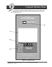
Using the Menu Options
The UPS menus allow you to display data in the information area to help you
monitor and control UPS operation. The following menus and options are
available:
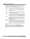
• Meters Displays UPS performance meters for the system or critical load.
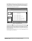
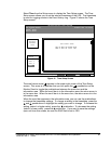
• Events Displays the list of Active System Events and a historical log of
system events.
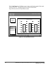
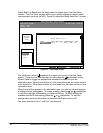
• Statistics Displays statistical information about UPS operations for the
battery, load, or line.
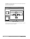
• Graphics Displays a real-time graphic representation of the flow of current
through the internal UPS components.
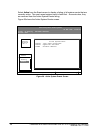
• Setup Allows you to configure the UPS communications port and set
the date and time for the timestamp.
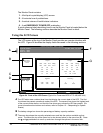
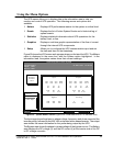
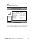
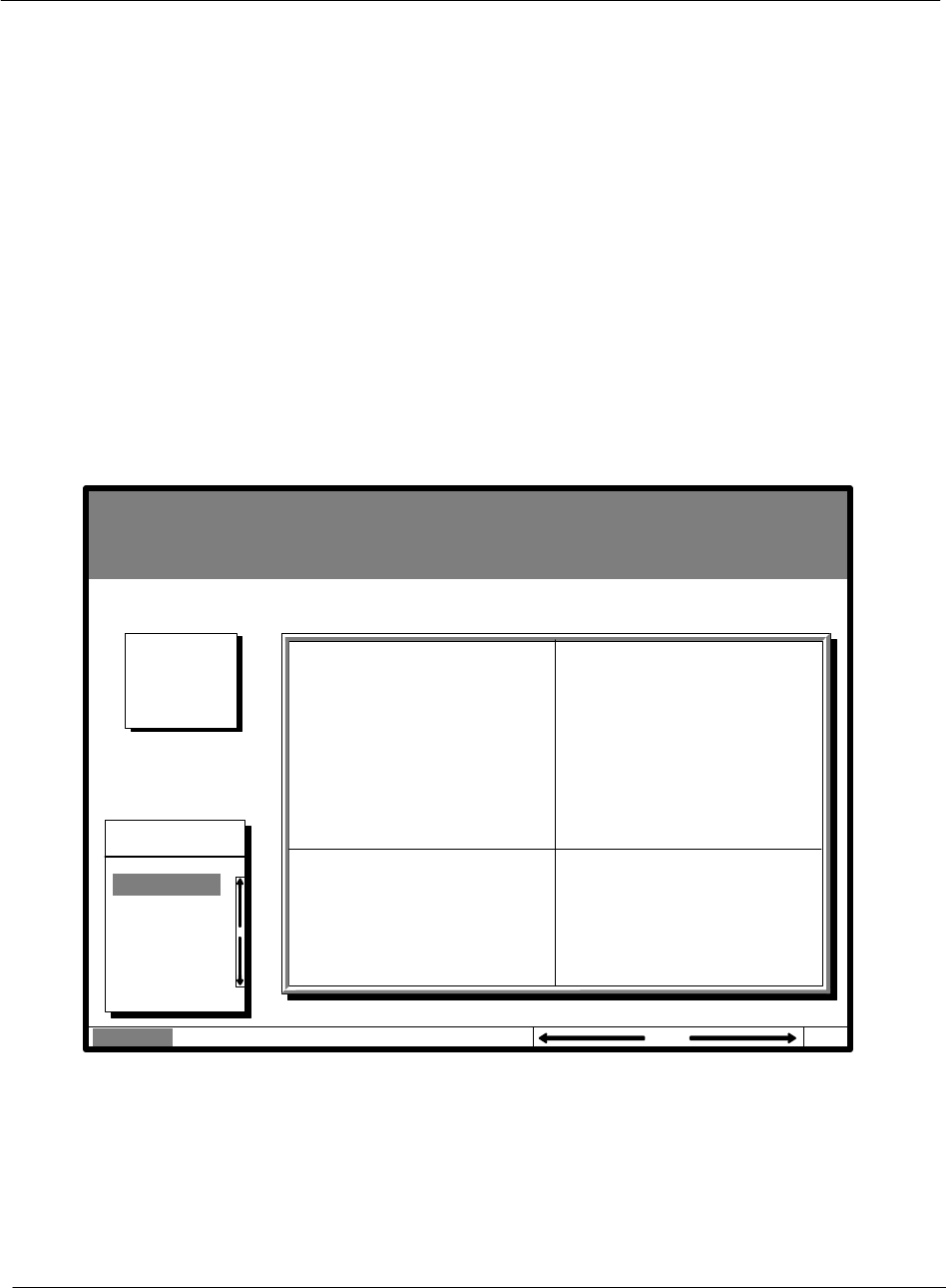
Figure 25 shows the LCD screen a s it appears when you first start the UPS. The Meters
menu is displayed in the menu box, with the System option highlighted. In the
information area, the system meters show their current readings.
Uninterruptible Power System
System Normal
Alarm: None
Notice: None
Meters
System
Load Amps
Events Statistics Graphics Setup
Input Output
Bypass Battery
VAB
480
VBC VCA
KW
69
KVA
73
IA IB IC
FREQ
60.0
PF
0.95
V
540
I
000
Meters
88
480 480
8888
VAB
480
VBC VCA
480 480
IA IB IC
90 9090
IN
000
VAB
480
VBC VCA
480 480
FREQ
60.0
KVA
75
KW
60
PF
0.80
Battery
04 MAY 1998 14:25:45
100%
Percent
Figure 25. System Meters Screen (Typical for Powerware BPIII HE 75 480/480V Unit)
The Input area shows the phase-to-phase voltage, frequency, and phase current of the
incoming utility, followed by the KVA, KW, and power factor measurements. The output
area shows the same information for the power being output by the UPS.
TheBypassareashowsthephase-to-phasevoltageofthebypasssource. TheBattery
area displays the DC voltage (V) and the DC current (I) at the inverter side of the DC
to DC voltage converter.