


vii
Powerware BPIII Harsh Environment UPS 50--75 kVA Installation and Operation
164201261 Rev. F 111503
List of Figures
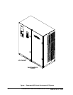
Figure 1. Powerware BPIII Harsh Environment UPS System 2.........
Figure 2. Cabinet as Shipped, with Outer Packaging and Pallet 10......
Figure 3. Rem oving Front and Rear Supports 12......................
Figure 4. UPS and Environmental Cabinets 13........................
Figure 5. C abinet-to-Cabinet Grounding 15..........................
Figure 6. Remote EPO Control 21...................................
Figure 7. Remote Monitor Panel (R MP) 24...........................
Figure 8. Te rminal Block Bracket 25.................................
Figure 9. Wiring an RMP to the UPS 26..............................
Figure 10. Relay Interface Module 29.................................
Figure 11. Terminal Block Bracket 30.................................
Figure 12. Wiring an RIM to the UPS 31...............................
Figure 13. Supervisory Contact Module 33............................
Figure 14. Terminal Block Bracket 34.................................
Figure 15. Wiring an SCM to the UPS 35..............................
Figure 16. Supervisory Contact Module TB2 36........................
Figure 17. Main Elements of the UPS System 40.......................
Figure 18. Path of Current Through the UPS in Normal Mode 41.........
Figure 19. Path of Current Through the UPS in Bypass Mode 42.........
Figure 20. Path of Current Through the UPS in Battery Mode 43.........
Figure 21. Path of Current Through the UPS in Maintenance
Bypass Mode 44.........................................
Figure 22. Location of the Monitor Panel and the Control Panel 45.......
Figure 23. UPS Monitor Panel 51....................................
Figure 24. Parts of the LCD Screen
(Typical for P owerware BPIII HE 75 480/480V Unit) 52.........