


88
Powerware BPIII Harsh Environment UPS 50--75 kV Installation and Operation
164291261 Rev. F 111503
3
2
1
6
5
4
9
8
7
12
11
10
13
15
14
18
17
16
21
20
19
24
23
22
25
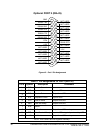
GND
RS232 TXD
RS232 RXD
RS232 RTS
RS232 CTS
RS232 DSR
RTN
+12V
NOT USED
NOT USED
NOT USED
NOT USED
NOT USED
NOT USED
NOT USED
NOT USED
NOT USED
NOT USED
NOT USED
RS232 DTR
NOT USED
--12V
NOT USED
NOT USED
NOT USED
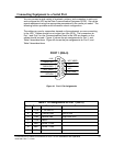
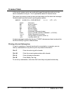
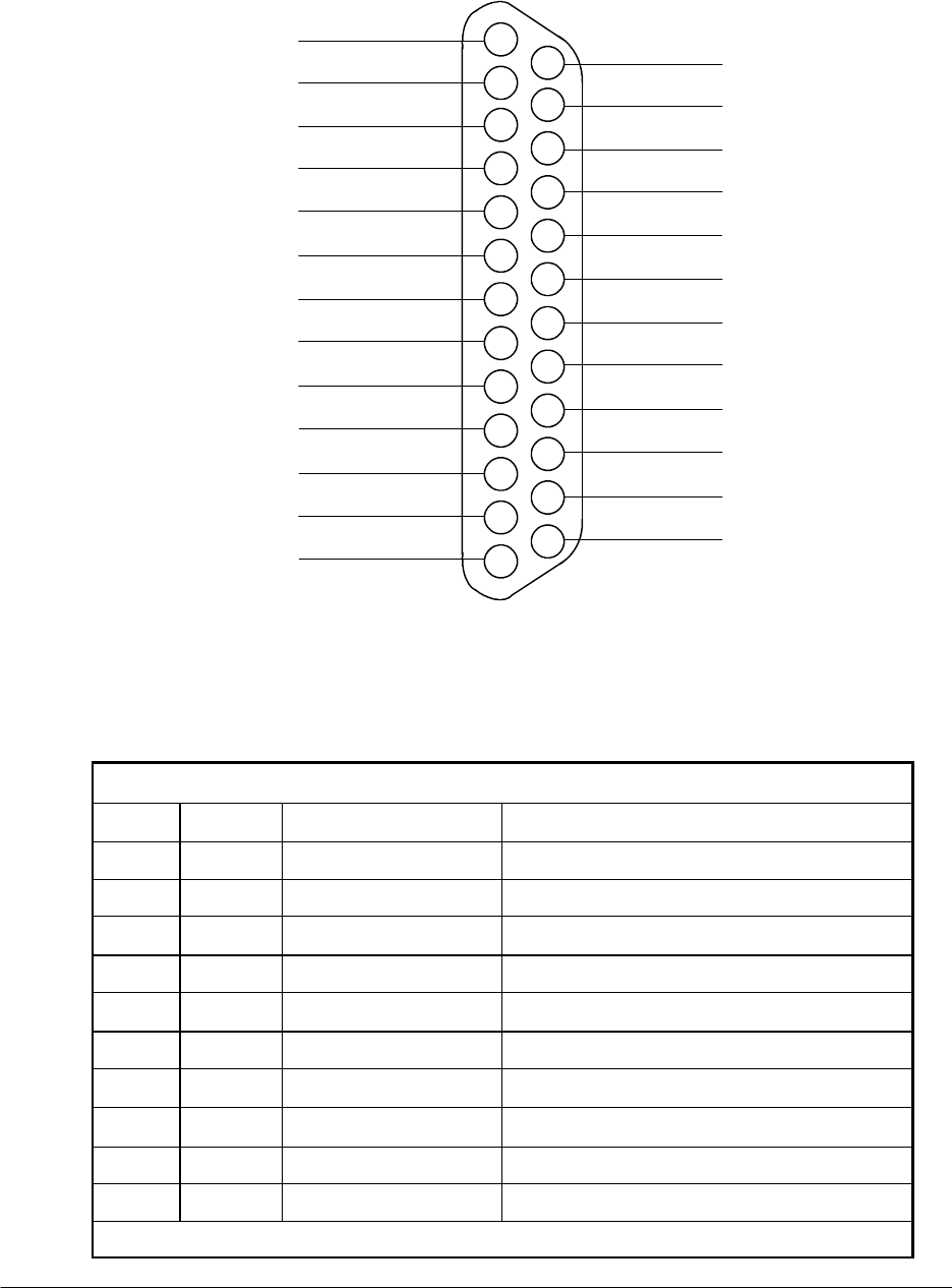
PORT 2 (DB--25)Optional
Figure 42. Port 2 Pin Assignments
Table 3. Pin Assignments for Port 2 (DB---25)
Pin # Symbol Description Co mments
1 GND Chassis Ground
2 TXD Transmit Data Input to UPS
3
RXD Receive Data Output from UPS
4 RTS Request to Send Input to UPS
5
CTS Clear to Send Output from UPS
6 DSR Data Set Ready Output from UPS
7
RTN Return
8
+12V +12 volts Output from UPS --- always true
20 DTR Data Terminal Ready Input to UPS --- typically not used by U PS
22 --- 1 2V --- 12 volt s Output from UPS --- always true
NOTE: Pins 5 and 6 are tied together internally.