


71
Powerware BPIII Harsh Environment UPS 50--75 kVA Installation and Operation
164201261 Rev. F 111503
Using Features and Options
The many standard features of your UPS provide consistent,
economical, and dependable power protection. In addition, you
can add available options and accessories to enhance the performance of your
UPS system. This chapter provides detailed descriptions of some of the features
and options introduced earlier in this manual.
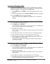
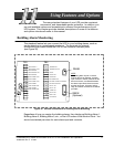
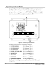
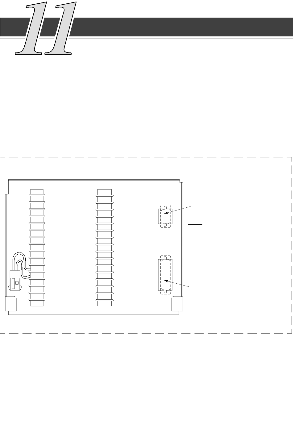
Building Alarm Monitoring
This standard feature lets you connect the UPS to your building alarms, such as
smoke detectors or overtemperature alarms. The terminals for external
connections are located inside the UPS on the customer interface panel
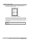
(see Figure 35).
TB1
BLDG ALARM 1
BLDG ALARM 4
BLDG ALARM 5
NOTE:
All building alarm inputs or remote
features require an isolated, no rmally
open contact or switch ( rated at 24 Vdc
20 mA minimum) connected between
the alarm input terminal and common
terminal as shown. All c ontrol wiring,
relay, and switch c ontacts are customer
provided.
1
2
3
4
5
6
7
8
9
15
10
11
14
13
12
TB2
BLDG ALARM 2
BLDG ALARM 3
BLDG ALARM 6
1
2
3
4
5
6
7
8
9
15
10
11
14
13
12
RS232
RS485
ON BYP ASS
BATTERY CONTACTOR CLOSED
RELAY2 NO
ON INV
RELAY2 NC
RELAY1 NO
RELAY1 NC
BLDG ALARM 1 RTN
BLDG ALARM 4 RTN
BLDG ALARM 5 RTN
BLDG ALARM 2 RTN
BLDG ALARM 3 RTN
BLDG ALARM 6 RTN
REMOTE EPO
REMOTE EPO RTN
ON BYP ASS RTN
BATTERYCONTRTN
ON INV RTN
ALARM RTN
NOTICE RTN
(Optional)
Figure 35. External Connections for Building Alarm Monitoring
Regardless of how you assign the building alarms, they display as Building Alarm 1,
Building Alarm 2, Building Alarm 3, etc., on the LCD screen of the Monitor Panel. You
should use twisted pair wires for each alarm input and common.