


DESCRIPTION:
DATE:
DRAWING NO:
10 of 11
INSTALLATION NOTES
SHEET:
REVI SION:
A
053099
164201261---1
A --- 11
Powerware BPIII Harsh Environment UPS 50--75 kVA Installation and Operation
164201261 Rev. F 111503
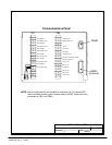
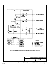
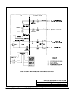
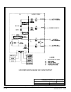
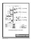
28. Use Class 1 wiring methods (as defined by the NEC) for control wiring. Install the control
wiring in separate ferrous conduit from the power wiring. The wire should be rated at 24
volts, 1 amp minim um . Control wiring and conduit to be supplied by designated personnel.
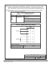
29. Refer to Tables L, M, and N, and to applicable chapters for information about installing
control wiring for options and accessories.
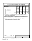
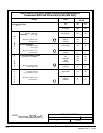
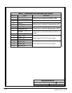
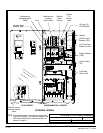
Table L. Control Wiring Terminations
g
Terminal Description Terminal Function
T
B
1
T
e
r
m
i
n
a
l
B
l
o
c
k
N
o
t
a
v
a
i
l
a
b
l
e
t
o
c
u
s
t
o
m
e
r
T
B
1
T
erm
i
na
l
B
l
oc
k
N
ot a
v
a
i
l
a
b
l
etocustomer
TB1 Terminal Block
Remote EPO
TB2
T
B
2
“On Inverter” Monitoring
TB2
“On Bypass” Monitoring
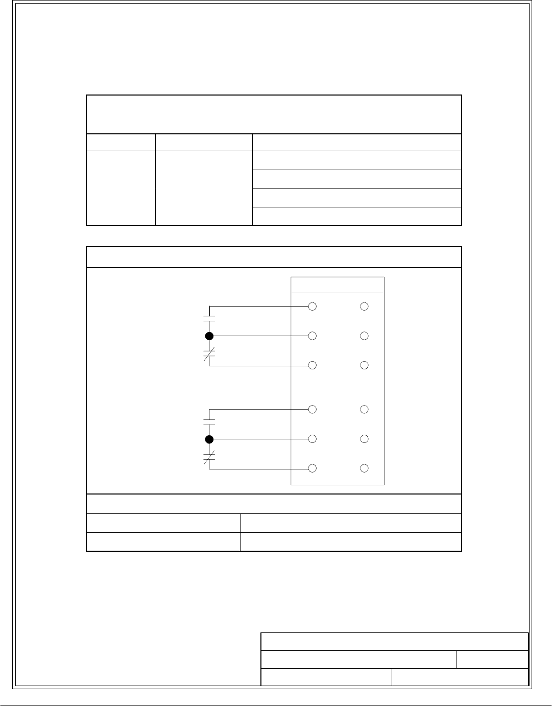
Summary Alarm & Notice Contacts
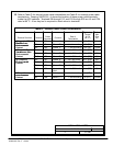
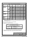
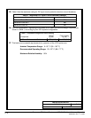
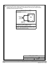
Table M. Summary Alarm Relay Co ntacts
CONTACT RATING:
Maximum Switched Voltage 32 VAC 42 VDC
Maximum Carrying Current 1A
14
15
13
11
12
10
RELAY 1
TB2
RELAY 2