


87
Powerware BPIII Harsh Environment UPS 50--75 kVA Installation and Operation
164201261 Rev. F 111503
Connecting Equipment to a Serial Port
You can connect a wide variety of terminals, printers, and computers to each port,
and configure the UPS as the Data C ommunication Equipment (DCE). S et up the
remote equipment using the appropriate parameters for the mode you select. The
following section provides more information about configuration.
The cables you use for connection depend on the equipment you are connecting
to the UPS. Cables should be no longer than 16m (50 ft). The connectors for
Port 1 and Port 2 on the Communications Panel in the UPS are female, so the
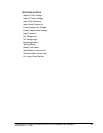
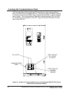
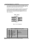
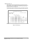
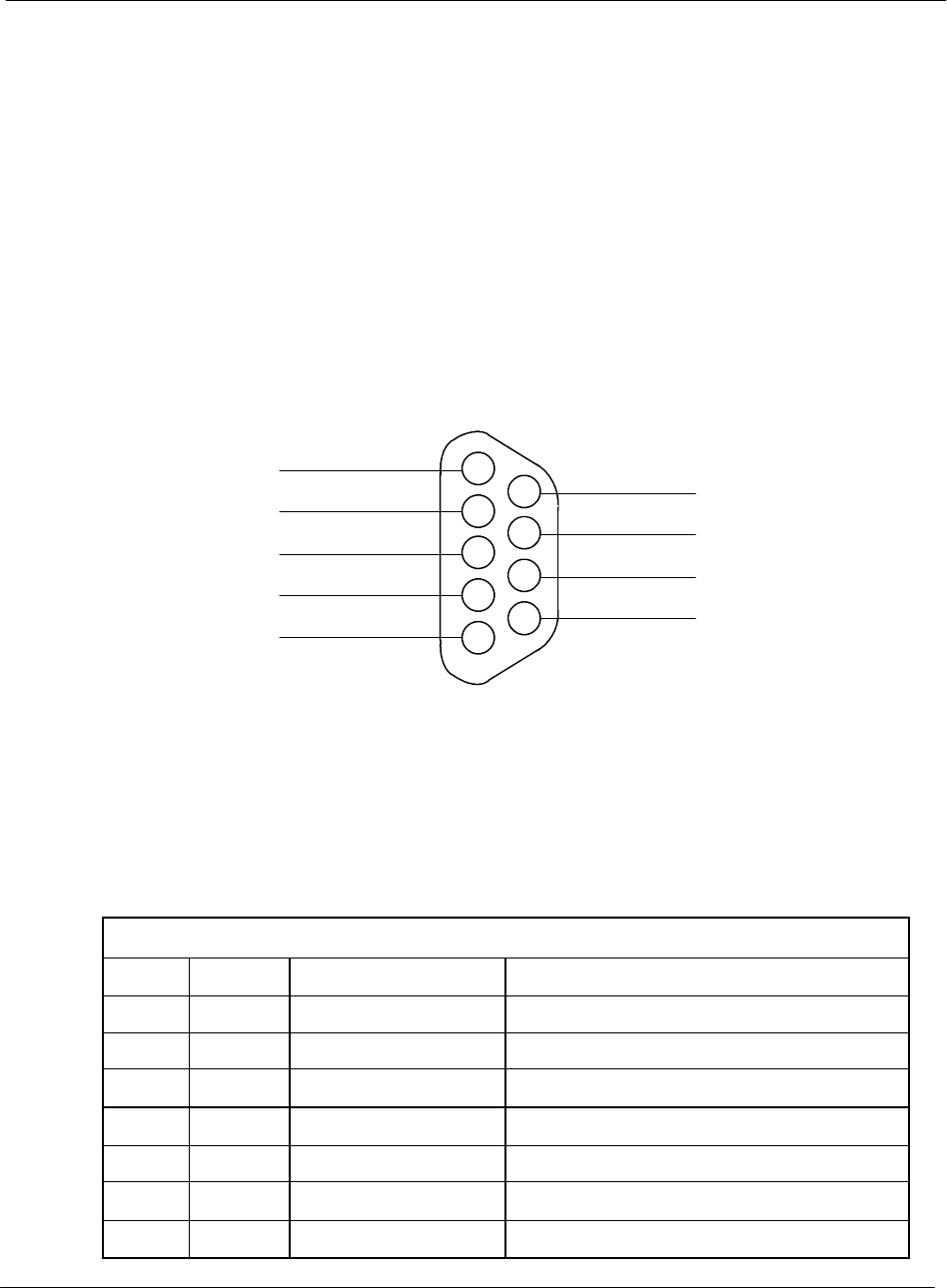
cables should be male. Figure 41 shows the pin assignments for Port 1, and
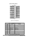
Table 2 describes them. Figure 42 shows the pin assignments for Port 2, and
Table 3 describes them.
3
2
1
5
4
7
6
9
8
+24V
RS232 TXD
RS232 RXD
NOT USED
RETURN
NOT USED
485 +
485 --
RETURN
PORT 1 (DB--9)
Figure 41. Port 1 Pin Assignments
Table 2. Pin Assignments for Port 1 (DB---9)
Pin # Symbol Description Co mments
1 +24V +24voltsDC
2 TXD Transmit Data Input to UPS
3
RXD Receive Data Output from UPS
5
RTN Return
7 485+ RS485 + Data
8
485--- RS485 --- Data
9
RTN Return