


32 Powerware BPIII Harsh Environment UPS 50--75 kV Installation and Operation
164291261 Rev. F 111503
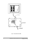
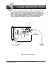
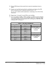
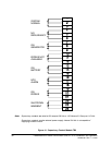
4. Connect RIM wiring to the terminal block using the terminations shown in
Table E.
5. Contact your local field service office for verification and testing of the RIM
and its connections prior to making connections with J1---J4.
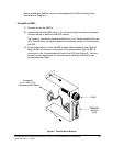
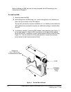
You can order interface cables separately for connecting to the 15-Pin D-Sub
Connectors.
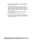
6. Repeatsteps1through5foreachRIMyouareinstalling.
7. If you are installing an RMP or SCM in addition to an RIM, proceed to Chapter
4 or 6, respectively; otherwise, secure the UPS cabinet by reversing the steps
contained in procedure “To Prepare the UPS for Wiring to an RMP, RIM, SCM,
or Remote EPO” of Chapter 2.
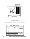
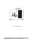
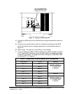
Tab le E . RIM Wi re Te rmi nat ion s
From RIM A To UPS Remarks
TB 1 --- 4
TB 3 --- 1
T
W
I
S
T
E
D
W
I
R
E
S
(
4
)
TB 1 --- 5
TB 3 --- 2
TWISTED WIRES (4)
1 --- 2 TU R N S PE R
TB 1 --- 6
TB 3 --- 3
1
2
T
U
R
N
S
P
E
R
3INCHES
TB 1 --- 7
TB 3 --- 4
From RIM B (if used) To UPS Remarks
TB 1 --- 4
TB 3 --- 5
T
W
I
S
T
E
D
W
I
R
E
S
(
4
)
TB 1 --- 5
TB 3 --- 6
TWISTED WIRES (4)
1 --- 2 TU R N S PE R
TB 1 --- 6
TB 3 --- 7
1
2
T
U
R
N
S
P
E
R
3INCHES
TB 1 --- 7
TB 3 --- 8