


DESCRIPTION:
DATE:
DRAWING NO:
4of11
INSTALLATION NOTES
SHEET:
REVI SION:
B
011500
164201261---1
A---5
Powerware BPIII Harsh Environment UPS 50--75 kVA Installation and Operation
164201261 Rev. F 111503
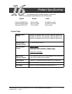
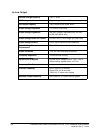
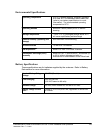
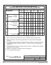
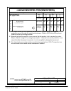
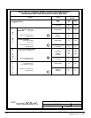
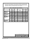
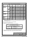
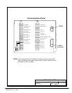
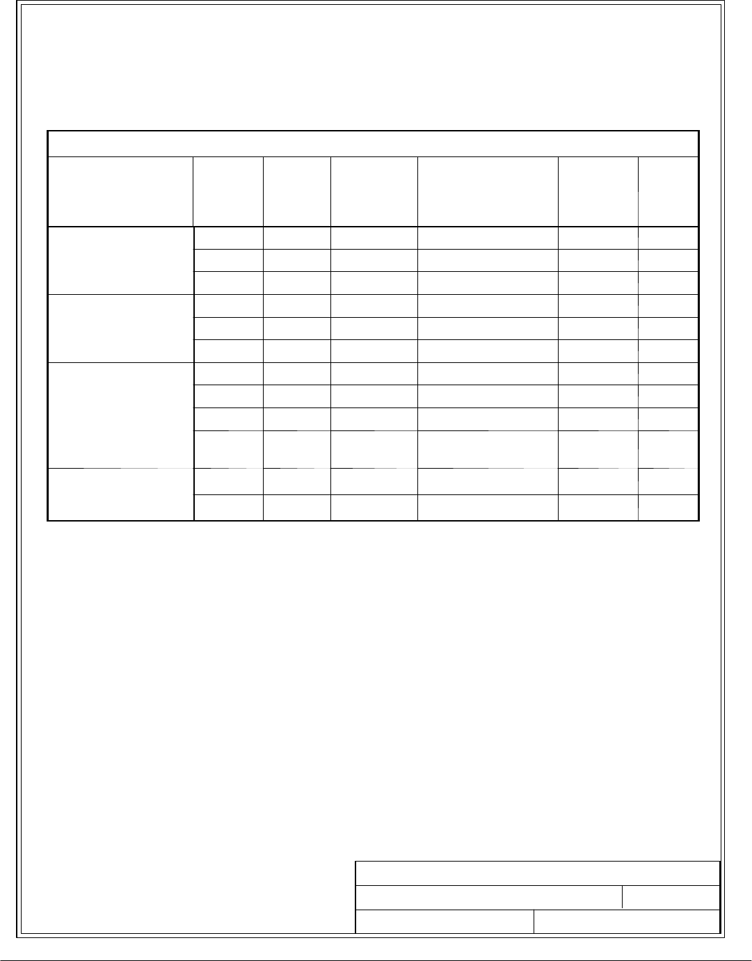
10. Refer to Table D for internal power cable terminations and Table E for external power cable
terminations. Drawing 164201014---4 shows the location of these power cable terminals
inside the UPS cabinets. Terminals E9 through E15, and E19 through E35 are UL and CSA
rated at 90˚C. A hex key tool is required to attach wires to terminals.
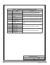
Table D. Internal Power Cable Terminations
Terminal Function Terminal
Cable
Number
Function
Size of
Termination
Tightening
Torque
N --- M
(l b --- in )
Bolt or
Hex
Size
(In.)
AC Input to UPS
R
e
c
t
i
f
i
e
f
o
E1 250 Phase ‘A’ 1 --- 1 bolt mou nt in g 9.0 (78) 1/4 bolt
Rectifier from
E
n
v
i
r
o
n
m
e
n
t
a
l
E2 251 Phase ‘B’ 1 --- 1 bolt mou nt in g 9.0 (78) 1/4 bolt
E
n
v
i
r
o
n
m
e
n
t
a
l
Cabinet
E3 252 Phase ‘C’ 1 --- 1 b olt mou n ti ng 9.0 (78) 1/4 bolt
AC Input to By pass
T
a
s
f
o
e
f
o
E13 227 Ph ase ‘A’ 1 --- # 4 --- 50 0 kcm il 42.4 (375) 3/8
Transformer from
E
n
v
i
r
o
n
m
e
n
t
a
l
E14 228 Ph ase ‘B’ 1 --- #4 --- 50 0 k cm il 42.4 (375) 3/8
E
n
v
i
r
o
n
m
e
n
t
a
l
Cabinet
E15 229 Ph ase ‘C’ 1 --- # 4 --- 5 00 kcm il 42.4 (375) 3/8
AC Output to
E
i
o
e
t
a
l
E9 237 Phase ‘A’ 1 --- # 6 --- 3 50 kcm il 31.1 (275) 3/8
Environmental
C
a
b
i
n
e
t
E10 238 Ph ase ‘B’ 1 --- #6 --- 35 0 k cm il 31.1 (275) 3/8
C
a
b
i
n
e
t
E11 239 Ph ase ‘C’ 1 --- # 6 --- 3 50 kcm il 31.1 (275) 3/8
E12 600 Ne utral/
Gnd.
2 --- # 4 --- 5 00 kcm il 31.1 (275) 3/8
DC Input from
E
n
v
i
r
o
n
m
e
n
t
a
l
E4 205 Battery (+) 1 --- 1 bolt mou n ti ng 32 (277) 3/8 bolt
E
nv
i
ronmen
t
a
l
Cabinet
E5 206 B at te r y ( --- ) 1 --- 1 bolt mou nt in g 32 (277) 3/8 bolt