


52
Powerware BPIII Harsh Environment UPS 50--75 kV Installation and Operation
164291261 Rev. F 111503
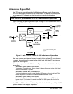
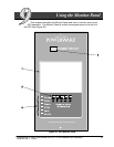
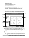
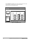
The Monitor Panel contains:
1. A flat liquid crystal display (LCD) screen.
2. A horizontal row of pushbuttons.
3. A vertical column of backlit status indicators.
4. AredEMERGENCY POWER OFF pushbutton.
A quick reference label describing how to use the Monitor Panel is located below the
Monitor Panel. The following sections describe the Monitor Panel in detail.
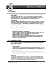
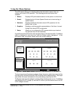
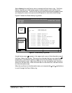
Using the LCD Screen
The LCD screen at the top of the Monitor Panel provides an operator interface with
the UPS. Figure 24 identifies the display fields discussed in the following sections.
Uninterruptible Power System
System Normal
Alarm: None
Notice: None
Meters
System
Load Amps
Events Statistics Graphics Setup
Input Output
Bypass Battery
VAB
480
VBC VCA
KW
69
KVA
73
IA IB IC
FREQ
60.0
PF
0.95
V
540
I
000
Meters
88
480 480
8888
VAB
480
VBC VCA
480 480
IA IB IC
90 9090
IN
000
VAB
480
VBC VCA
480 480
FREQ
60.0
KVA
75
KW
60
PF
0.80
Battery
04 MAY 1998 14:23:45
100%
Percent
A
E
D
C
B
F
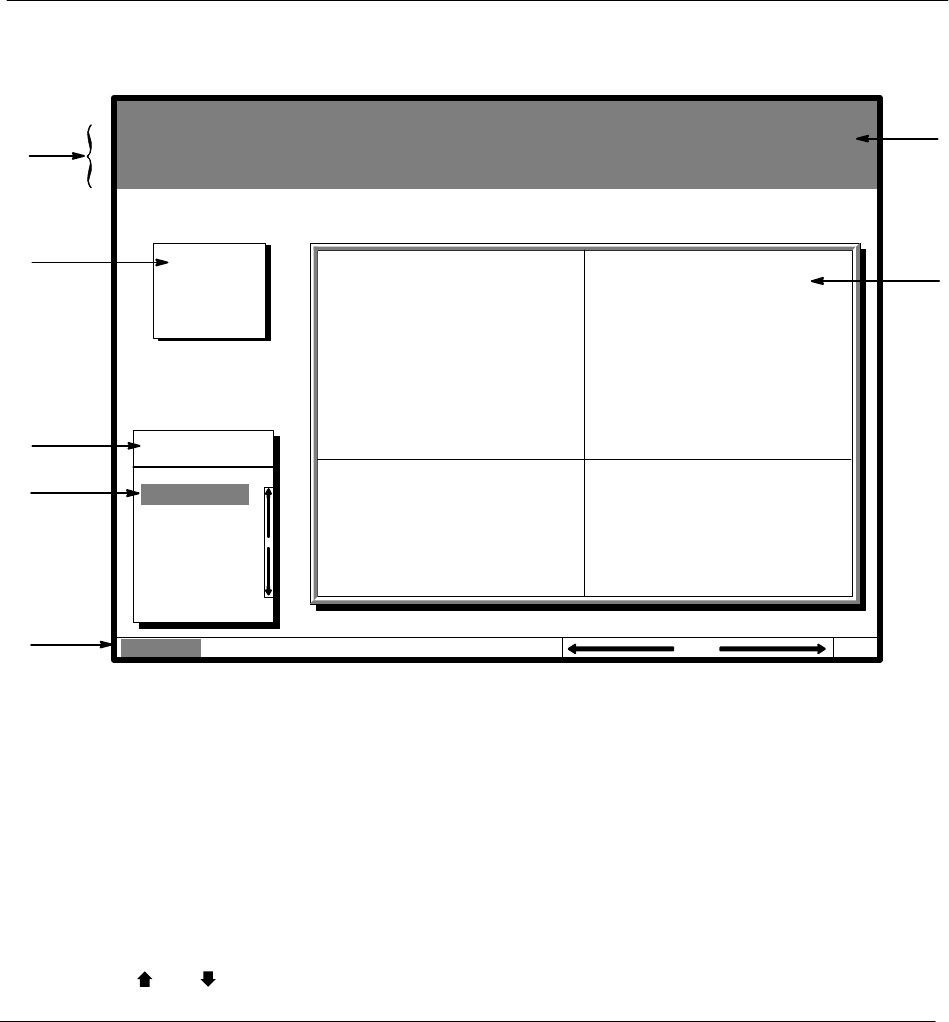
G
Figure 24. Parts of the LCD Screen (Typical for Powerware BPIII HE 75 480/480V Unit)
A The UPS status area contains three lines that display the current state of the UPS. The first
line shows the present operational mode of the UPS. The second line shows the highest level
of the current active alarms, and the third line shows any notices the UPS has posted. (For
more information about alarms and notices, refer to Chapter 12 --- Responding to System
Events.)
B The battery charge box shows the percentage of battery capacity available.
C The menu box shows the currently selected menu and lists the options available on that
menu. The title at the top of the menu box is also shown below on the menu bar (E). Press
the
and pushbuttons to scroll up and down through the options in the menu box.