


A --- 19
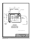
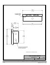
Powerware BPIII Harsh Environment UPS 50--75 kVA Installation and Operation
164201261 Rev. F 111503
DESCRIPTION:
DATE:
DRAWING NO:
2of2
SHEET:
REVI SION:
A
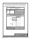
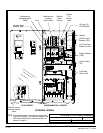
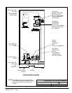
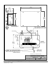
LOCATION OF UPS POWER TERMINALS
053099
TB1
TB2
Ground
DC Input to UPS
(E4, E5)
(+ , --- )
Connect cables
205 and 206
AC Input to
Bypass Transformer
(E13, E14, E15)
(A,B,CLefttoRight)
Connect cables 227,
228, and 229
Por t 1 (DB --- 9)
RS---232/485
(J3)
Communication
Panel
Por t 2 (DB --- 25 )
R S --- 23 2
(J4)
(Optional)
Main Bonding
Jumper
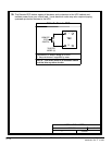
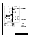
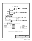
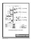
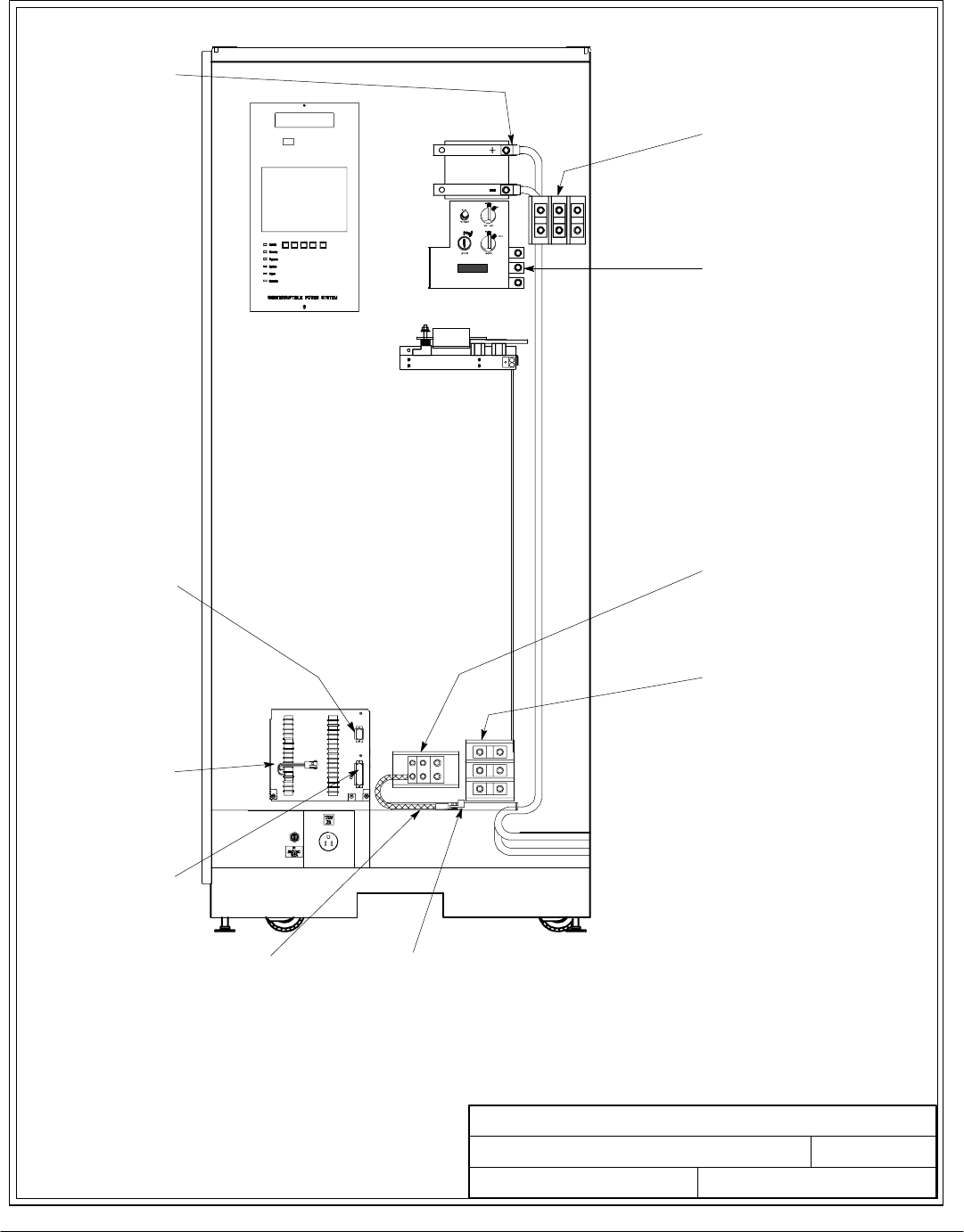
INTERCABINET WIRING
AC Input to
UPS Rectifier
(E1, E2, E3)
(A,B,CToptoBottom)
Connect cables 250,
251, and 252
Output
Neutral
Connection
(E12)
Connect cable 600 (2)
AC Output
(E9, E10, E11)
(A,B,C,
Top to Bottom
Connect cables
237, 238, and 239
164201261---4
NOTE:
Connections shown are between the
UPS cabinet and Environmental cabinet.
External connections are shown on
sheet 1.