


( 29 / 76 )
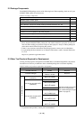
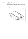
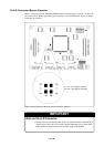
(3) Using the Oscillator Circuit Bare Board
The oscillator circuit board OSC-3 (for 30 MHz) is preinstalled to the emulator main unit. To use it
at 32 MHz, replace the board with the included OSC-3 (for 32 MHz). To use it at a frequency other
than 30 or 32 MHz, build a desired oscillator circuit on the included OSC-2 oscillator circuit bare
board.
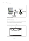
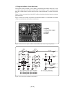
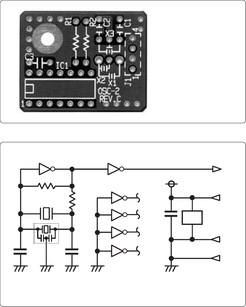
Figure 3.3 shows an external view of the OSC-2 oscillator circuit bare board and where the connector
pins are located.
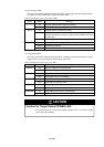
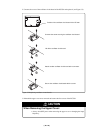
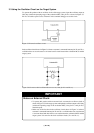
Figure 3.4 shows the circuitry of oscillator circuit bare board OSC-2. Use the number of oscillator
circuits recommended by the oscillator manufacturer.
Figure 3.3 External view of the oscillator board (OSC-2) and connector pin assignments
J1-4: GND
Figure 3.4 Circuit of the oscillator board (OSC-2)
J1-3: Oscillator output
J1-2: GND
J1-1: Vcc
* X1: 5.08-mm-pitch 2-pin oscillator IC1: Inverter (Unbuffer)
* X2: 2.54-mm-pitch 2-pin oscillator
* X3: 2.54-mm-pitch 3-pin oscillator
IC1
R1
C2
C1
X1 ,X2
CLK
Vcc
GND
R2
J1-3
1011 8
9
2
1
4
3
6
5
12
13
C3
IC1
J1-1
J1-2
J1-4
GND
IC
1
**
X3
*
IC1
14
7