


( 30 / 76 )
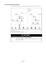
3.3 Using the Oscillator Circuit on the Target System
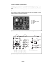
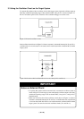
To operate this product with an oscillator circuit of the target system, input the oscillator output at
50% duty (within the operating range of the evaluation MCU) into pin XIN as shown in Figure 3.5.
Pin XOUT should be open. Choose "External" in the emulator debugger to use this clock.
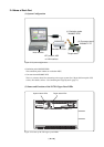
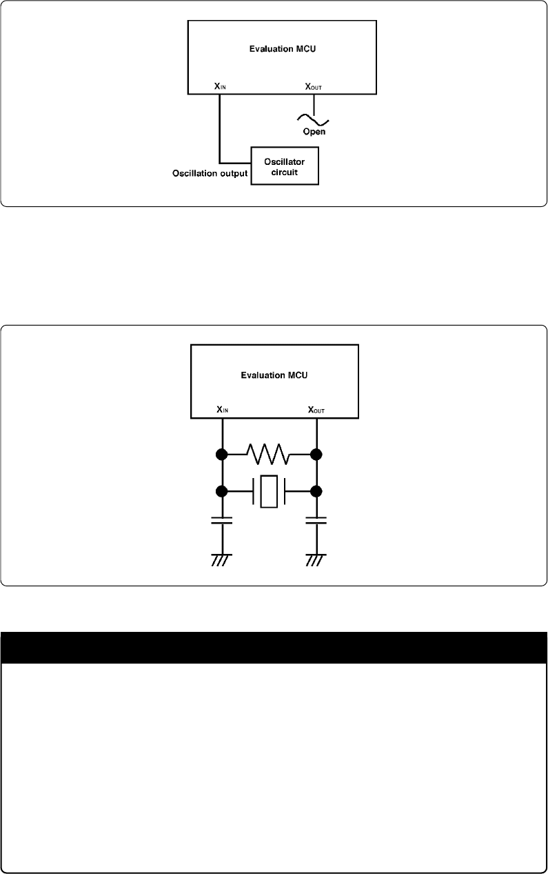
Figure 3.5 External oscillator circuit
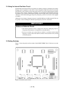
In the oscillator circuit shown in Figure 3.6 where a resonator is connected between pins XIN and XOUT,
oscillation does not occur because a converter board is used between the evaluation MCU and the
target system.
Figure 3.6 Circuit in which oscillation does not occur (same for XCIN and XCOUT)
IMPORTANT
Notes on External Clock:
• To operate this product with an external clock, construct the oscillator circuit as
shown in Figure 3.5 in the target system and input the oscillator output at 50% duty
(within the operating range of the evaluation MCU) into pin XIN. And pin XOUT
should be open.
• Make note of the fact that in the oscillator circuit shown in Figure 3.6 where a
resonator is connected between pins XIN and XOUT, oscillation does not occur because
a converter board and other devices are used between the evaluation MCU and the
target system. It is same for sub-clock oscillator circuits (XCIN and XCOUT).