


( 31 / 76 )
3.4 Using the Internal Oscillator Circuit
The dedicated circuit in the PC7501 can generate any arbitrary frequency specified by the emulator
debugger, and it is supplied as a main clock. It does not depend on either the oscillator circuit board
in the PC7501 or the oscillator circuit on the target system. If you want to debug programs without
the target system or change a frequency temporarily, you can check its operation before preparing
an oscillator. If you want to use the internal oscillator circuit of the PC7501 as a main clock, choose
"Generate" in the emulator debugger and specify a frequency you like to use for this clock supplied
to an MCU.
Although you can change a frequency between 1.0 and 99.9 MHz by 0.1 MHz for the PC7501, do
not specify a value exceeding the maximum input frequency of the XIN of the MCU.
IMPORTANT
Notes on External Clock:
• The internal generator circuit is equipped for temporary debugging purposes.
Temperature characteristics of frequencies are not guaranteed.
• Be sure to evaluate your system with an oscillator or oscillator module whose
frequency is same as that of the internal oscillator circuit (internal clock) for final
evaluation purposes.
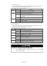
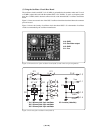
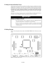
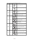
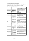
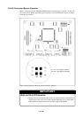
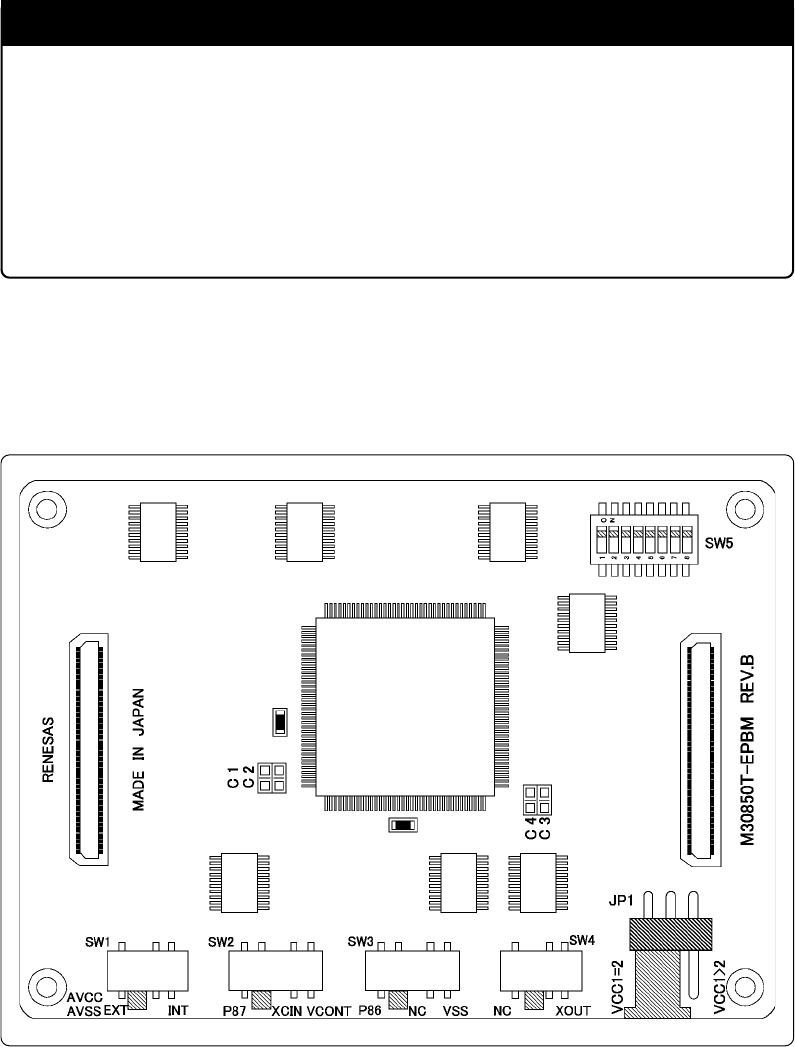
3.5 Setting Switches
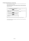
Figure 3.7 shows the positions of the switches of the M30850T-EPBM. Table 3.2 lists how to set each
switch.
Figure 3.7 Positions of the switches