


244
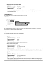
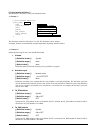
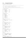
[( Cyclic handler definition )]
This definition is necessary to use Cyclic handler function.
<< Format >>
// Cyclic Handlar Definition
cyclic_hand[
ID No.
]{
name =
ID name
;
interval_counter =
Activation cycle
;
start =
TA_STA attribute
;
phsatr =
TA_PHS attribute
;
phs_counter =
Activation phase
;
entry_address =
Start address
;
exitf =
Extended information
;
};
:
:
The ID number must be in the range of 1 to 255. The ID number can be omitted.
If omitted, numbers are automatically assigned sequentially beginning with the smallest.
<< Content >>
Define the following for each cyclic handler ID number.
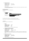
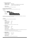
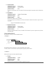
1. ID name
[( Definition format )]
Symbol
[( Definition range )] None
[( Default value )] None
Define the name by which the memory pool is specified in a program.
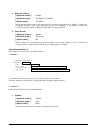
2. Activation cycle
[( Definition format )]
Numeric value
[( Definition range )] 1 to 0x7FFFFFFF
[( Default value )] None
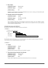
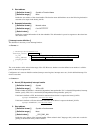
Define the activation cycle at which time the cyclic handler is activated periodically. The activation cycle here
must be defined in the same unit of time as the system clock's unit time that is defined in system clock definition
item. If you want the cyclic handler to be activated at 1-second intervals, for example, the activation cycle here
must be set to 1000.
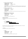
3. TA_STA attribute
[( Definition format )]
Symbol
[( Definition range )] ON or OFF
[( Default value )] OFF
Specify the TA_STA attribute of the cyclic handler. If ON is selected, the TA_STA attribute is added; if OFF is
selected, the TA_STA attribute is not added.
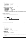
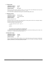
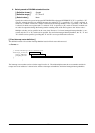
4. TA_PHS attribute
[( Definition format )]
Symbol
[( Definition range )] ON or OFF
[( Default value )] OFF
Specify the TA_PHS attribute of the cyclic handler. If ON is selected, the TA_PHS attribute is added; if OFF is
selected, the TA_PHS attribute is not added.