


Product Overview
1.4 Ethernet Panel Description
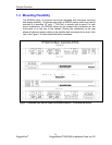
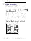
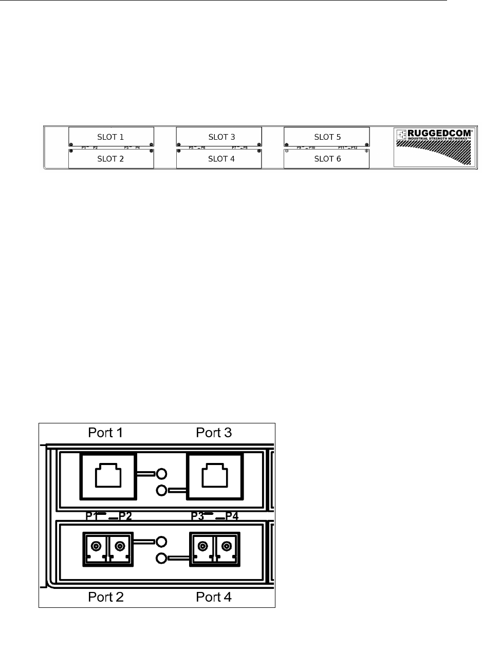
The Ethernet connector panel of the RSG2288 is organized into six slots, five of
which are modular and may be selected at the time the unit is ordered. Figure 2
shows the p
hysical layout of these ports.
Figure 2: RSG2288 Ethernet Port Layout
Slots 1, 2, 3 and 4 support two-port Ethernet modules up to 1Gbps. Slot 5
supports a one-port module up to 1Gbps. Slot 6 contains the PTP Source Card
(refer to 2.9 for details) to support advanced time synchronization.
Section 3.5 lists and provides specifications for the fiber optic interfaces available
for the RSG2200 series. The co
mplement of modules installed on a particular
unit may be determined by reading the factory data file via the RuggedSwitch
®
ROS
TM
user interface.
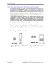
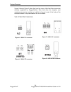
Each Ethernet port is equipped with an LED per port that indicates link/activity
status information. The LED is solid for ports with a valid link, and blinks for
activity. Figure 3 shows a copper port module in slot 1 and a fiber module in slot
2 along with
the associated link/activity LEDs for each port.
Figure 3: Ethernet panel LEDs
12
RuggedCom
®
RuggedSwitch
®
RSG2288 Installation Guide rev103