


Table of Figures
Table of Figures
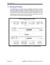
Figure 1: RSG2288 Rack mount chassis orientation options – Front and rear mount.... 11
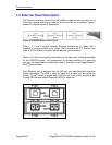
Figure 2: RSG2288 Ethernet Port Layout ....................................................................... 12
Figure 3: Ethernet panel LEDs........................................................................................ 12
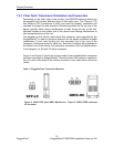
Figure 4: 1000LX SFP (mini-GBIC) Module and LC connector ......................................13
Figure 5: 1000LX GBIC connector.................................................................................. 13
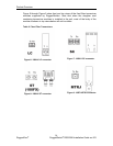
Figure 6: 1000LX LC connector ......................................................................................14
Figure 7: 1000LX SC connector......................................................................................14
Figure 8: 1000LX ST connector ......................................................................................14
Figure 9: 100FX MTRJ connector................................................................................... 14
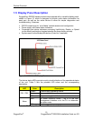
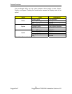
Figure 10: RSG2288 LED Display Panel ........................................................................ 15
Figure 11: RS2000 Family 19” Rack Mount Adapters.....................................................17
Figure 12: Rack mount adapter mounting location ......................................................... 17
Figure 13: RSG2200 PANEL/DIN RAIL mounting diagram ............................................18
Figure 14: RS2000 Series Philips Screw Terminal Block ............................................... 19
Figure 15: RS2000 Series Phoenix Plug Terminal Block................................................ 19
Figure 16: Chassis Ground Connection.......................................................................... 20
Figure 17: AC Single Power Supply Wiring Example...................................................... 21
Figure 18: AC Dual Redundant Power Supply Wiring Example...................................... 21
Figure 19: DC Power Supply Wiring Examples............................................................... 22
Figure 20: DC and AC Power Supply Wiring Examples..................................................23
Figure 21: Dielectric Strength (HIPOT) Testing .............................................................. 24
Figure 22: Failsafe Alarm Relay Wiring........................................................................... 25
Figure 23: Console port on display board ....................................................................... 26
Figure 24 : RS2000 Series Console cable...................................................................... 26
Figure 25 : RJ45 port pin configuration........................................................................... 27
Figure 26: SFP Orientation for top row and bottom row ports.........................................29
Figure 27: Locking latch location on GBIC optical modules............................................30
Figure 28: SFP Bail Latch location.................................................................................. 30
Figure 29: SFP Removal................................................................................................. 30
Figure 30: PTP Card Panel Description ..........................................................................32
Figure 31: IRIG-B Simplified Schematic.......................................................................... 35
Figure 32: RSG2288 Mechanical Dimensions ................................................................ 40
6
RuggedCo
m
®
RuggedSwitch
®
RSG2288 Installation Guide rev103