


Installation
2.6 Console Port Wiring
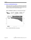
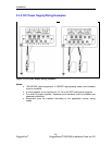
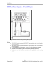
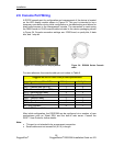
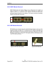
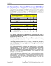
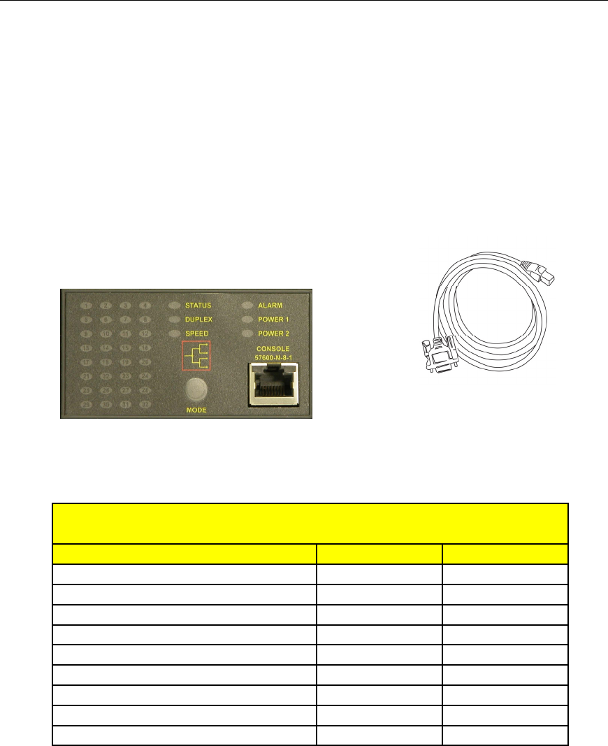
A RS232 console port for configuration and management of the device is located
on the LED display module shown in Figure 23. This port is intended to be a
temporary c
onnection during initial configuration or troubleshooting and allows for
direct serial access to the management console. The connection is made using
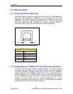
the DB9-Female to RJ45 console cable included in the device packaging shown
in Figure 24. Console connection settings are: 57600 baud, no parity bits, 8 data
bits, and 1 stop bit.
Figure 23: Console port on display board Figure 24 : RS2000 Series Console
cable
For user reference, the console cable pin-out is show in Table 6.
RuggedCom RS232 over RJ45 pin-out specification
Signal Name (PC is DTE) DB9- Female RJ45 Male
DCD – Carrier detect 1 2
RxD – Receive data (to DTE) 2 5
TxD – Transmit data (from DTE) 3 6
DTR – Data terminal ready 4 3
GND – Signal GND 5 4
DSR – Data set ready 6 1*
RTS – Ready to send 7 8
CTS – Clear to send 8 7
RI – Ring Indicator 9 1*
Table 6: RS232 over RJ45 console cable pin-out
After initial configuration, the RSG2288 can be configured via a number of new
mechanisms such as Telnet SSH, and the built-in web server. Consult the
ROS™ User Guide for further details.
Note:
This port is not intended to be a permanent connection.
Serial cable must not exceed 2m (6.5 ft) in length.
26
RuggedCom
®
RuggedSwitch
®
RSG2288 Installation Guide rev103