


Installation
2.9.1 PTP Card Panel Description
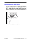
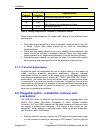
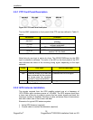
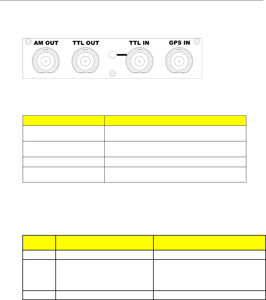
Figure 30: PTP Card Panel Description
The four BNC connectors on front panel of the PTP card are defined in Table 11,
below:
Connector Function
AM OUT
IRIG-B123 AM signal output, software
enabled
TTL OUT
IRIG-B003 PWM or 1 PPS signal output,
software selectable
TTL IN TTL-level IRIG-B PWM signal input
GPS IN
GPS antenna connector – please refer to
section 2.9.2 for detail.
Table 11: PTP Card Connectors
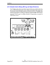
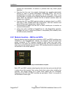
Note that only one input is active at a time. The IRIG-B PWM input or the GPS
input is selected in software. The color of the LED on the front panel of the PTP
card indicates the status of the incoming timing signal, depending on the input
selected:
Color GPS Input IRIG-B PWM Input
Green Lock Valid signal
Red Holdover mode (GPS lock has
been achieved but the receiver
no longer sees the minimum
number of required satellites.)
Problems with IRIG-B signal
Off No signal detected No signal detected
Table 12: PTP Card LED Functions
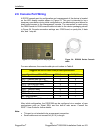
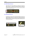
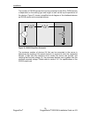
2.9.2 GPS Antenna Installation
The signals received from the GPS satellite network are at a frequency of
1575.42 MHz with a minimum power of -162 dBW. The GPS antenna must have
a clear view of the sky in order to receive the low power signals and track the
maximum number of satellites. Rooftops or other structures clear of obstructions
and with a clear view of the horizon are ideal.
Elements of a typical GPS antenna system:
Active GPS Antenna (required)
Coaxial cable to connect the elements (required)
32
RuggedCom
®
RuggedSwitch
®
RSG2288 Installation Guide rev103