


Installation
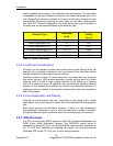
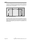
The number of IRIG-B d
evices that can be connected to the AM or PWM sources
is dependent on the cabling type and length as well as the input impedances of
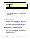
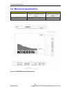
the devices. Figure 31 shows a simplified circuit diagram of the interface between
an IRIG-B s
ource and connected devices.
Vs
Rs Rc
R
L
/N
Source Cabling Device
Figure 31: IRIG-B Simplified Schematic
The maximum number of devices (N) that can be connected to the source is
determined by checking if the source current (I
S
) required to drive the connected
devices is less than the maximum drive current the source can provide, and
verifying that the load voltage (V
L
) the connected devices see is greater than the
minimum required voltage. Please refer to section 3.6.1 for specifications of the
IRIG-B outp
ut port.
35
RuggedCom
®
RuggedSwitch
®
RSG2288 Installation Guide rev103