


Installation
prevent the
accumulation of residue or particles that may inhibit proper
operation.
Ensuring that the user has properly discharged any possible electrostatic
build-up in order to prevent electrostatic discharges (ESD). This can be
accomplished by proper user ‘grounding’ via an ESD wrist strap, or by
touching earth or chassis ground before performing installation or removal of
optics. ESD can damage or shorten the life of optical modules when not
plugged into a chassis.
Ensuring that SFP and GBIC optical modules are always stored in an ESD-
safe bag or other suitable ESD-safe environment, free from moisture and
stored at the proper temperature (–40 to +85C).
Disconnecting all cables from the SFP or GBIC module prior to insertion or
removal of the module.
Using only optics certified by RuggedCom Inc. with RuggedCom products.
Damage can occur to optics and product if compatibility and reliability have
not been properly assessed.
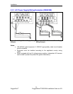
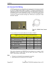
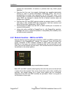
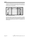
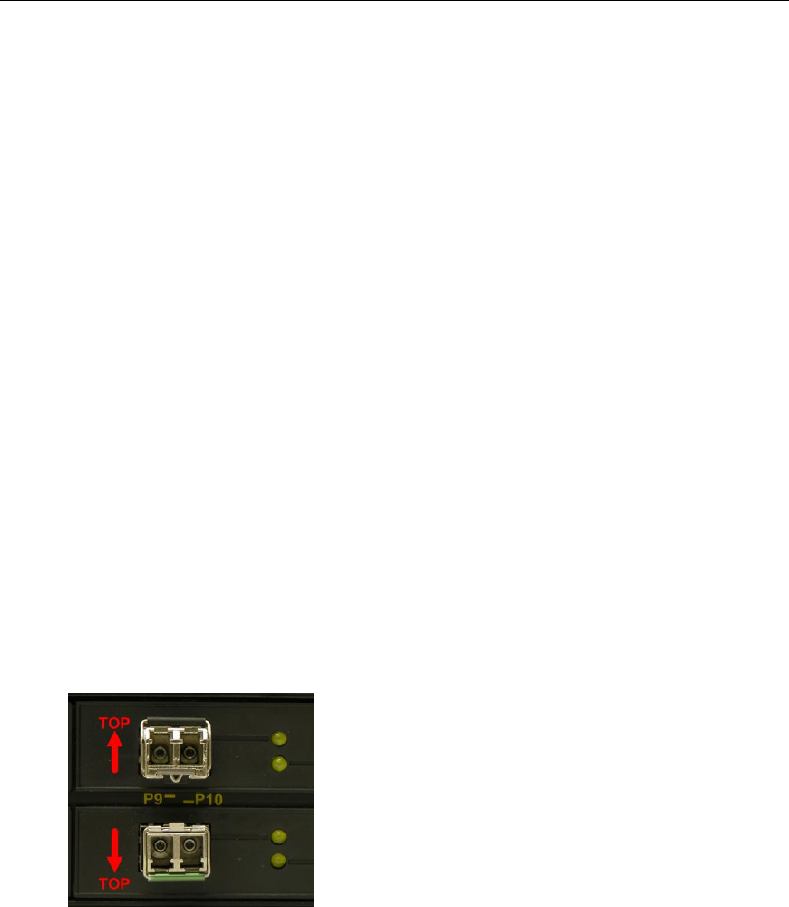
2.8.1 Module Insertion – GBICs and SFPs
Special attention must be paid to the orientation of SFP and GBIC modules upon
installation in the RuggedSwitch
®
chassis. For example, Figure 26 shows the
proper orientation of SFP modules installed to both upper and lower slots.
Modules on the upper row must be inserted top-side up, and modules on the
lower row must be inserted top-side down. SFP modules should be inserted with
the bail-latch in the locked position.
Figure 26: SFP Orientation for top row and bottom row ports
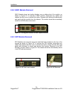
Both SFP and GBIC modules should gently slide into their ports and should lock
in place when fully inserted. Dust covers should be in place when installing the
modules, and should always be in place when cables are not connected.
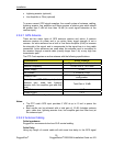
Diagrams of both SFP and GBIC modules are provided in Table 1 as a guide to
the orientation of each t
ype.
29
RuggedCom
®
RuggedSwitch
®
RSG2288 Installation Guide rev103