


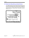
Installation
Lightning arrestor (optional)
Line Amplifier or Filter (optional)
To ensure correct GPS signal reception, the overall system of antenna, cabling,
lightning arrestor, line amplifier and filters requires a relative gain which should
be greater than 5 dBi but less than 18 dBi (to avoid signal saturation at the
receiver input).
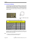
2.9.2.1 GPS Antenna
There are two major types of GPS antenna: passive and active. A passive
antenna requires no power and is an option when signal strength is not a
concern. An active antenna has a built in Low Noise Amplifier (LNA) to increase
the strength of the signal, and to compensate for the signal loss in a long cable
connection. Active antennas are used when the antenna input is connected to
the receiver through a coaxial cable (usually longer than 3 m) or any high loss
transmission path.
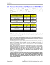
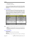
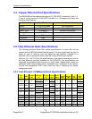
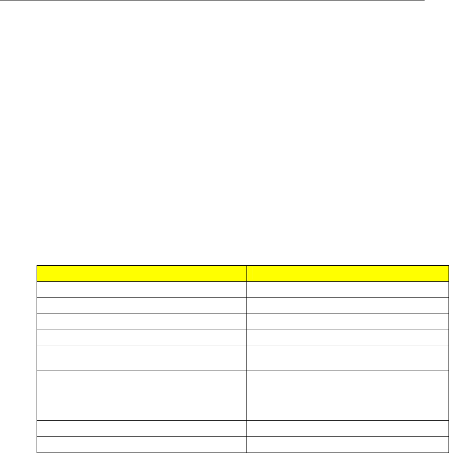
The PTP Card requires an active antenna with the following specifications:
Characteristic Active Antenna
Polarization Right-Hand Circular Polarized
Receive Frequency 1.57542 GHz ± 1.023 MHz
Power Supply 5 VDC
DC Current < 10 mA at 3 VDC
Antenna Gain
Select antenna gain based on system
configuration
Total Gain at PTP GPS Input (includes
antenna gain, cable loss, lightning
arrestor loss, line amplifier gain and filter
loss)
Total Gain ≤ 18 dBi
Axial Ratio < 3 dB
Output VSWR < 2.5
Table 13: GPS Antenna Specifications
Notes:
The PTP card’s GPS input provides 5 VDC at up to 10 mA to power the
antenna.
Best results can be achieved with a total gain of 16 dB (includes antenna
gain, cable loss, lightning arrestor loss, line amplifier gain and filter loss) at
the antenna input.
2.9.2.2 Antenna Cabling
Cable Impedance:
RuggedCom recommends low loss 50 Ω coaxial cabling.
Cable Delay
Using any length of coaxial cable will add some time delay to the GPS signal
33
RuggedCom
®
RuggedSwitch
®
RSG2288 Installation Guide rev103