SAM88RI INSTRUCTION SET S3C9228/P9228
6-4
FLAGS REGISTER (FLAGS)
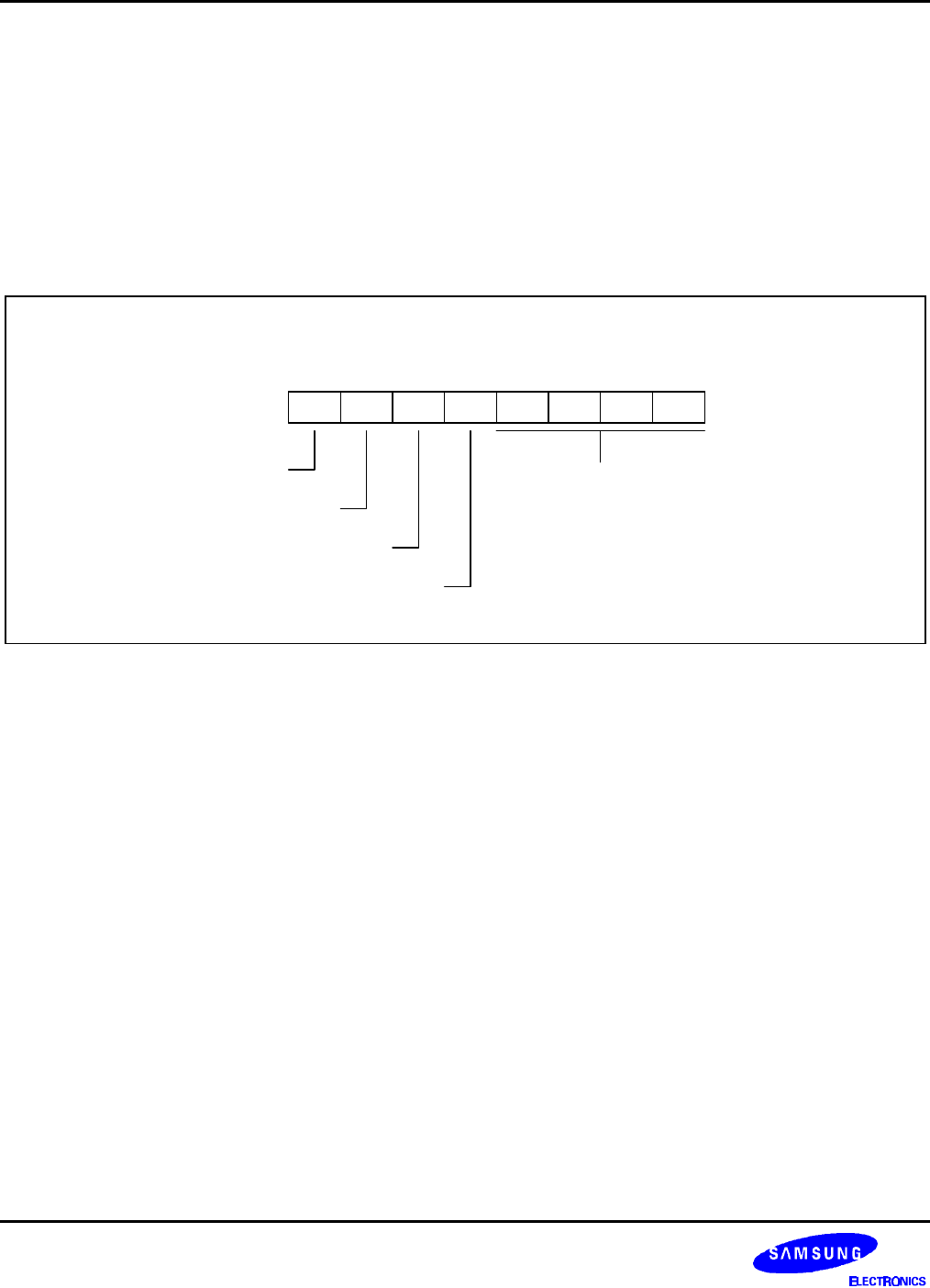
The FLAGS register contains eight bits that describe the current status of CPU operations. Four of these bits,
FLAGS.4 – FLAGS.7, can be tested and used with conditional jump instructions;
FLAGS register can be set or reset by instructions as long as its outcome does not affect the flags, such as, Load
instruction. Logical and Arithmetic instructions such as, AND, OR, XOR, ADD, and SUB can affect the Flags
register. For example, the AND instruction updates the Zero, Sign and Overflow flags based on the outcome of
the AND instruction. If the AND instruction uses the Flags register as the destination, then simultaneously, two
write will occur to the Flags register producing an unpredictable result.
.7 .6 .5 .4 .3 .2 .1 .0 LSBMSB
System Flags Register (FLAGS)
D5H, R/W
Not mapped
Carry flag (C)
Zero flag (Z)
Sign flag (S)
Overflow flag (V)
Figure 6-1. System Flags Register (FLAGS)
FLAG DESCRIPTIONS
Overflow Flag (FLAGS.4, V)
The V flag is set to "1" when the result of a two's-complement operation is greater than + 127 or less than – 128.
It is also cleared to "0" following logic operations.
Sign Flag (FLAGS.5, S)
Following arithmetic, logic, rotate, or shift operations, the sign bit identifies the state of the MSB of the result. A
logic zero indicates a positive number and a logic one indicates a negative number.
Zero Flag (FLAGS.6, Z)
For arithmetic and logic operations, the Z flag is set to "1" if the result of the operation is zero. For operations that
test register bits, and for shift and rotate operations, the Z flag is set to "1" if the result is logic zero.
Carry Flag (FLAGS.7, C)
The C flag is set to "1" if the result from an arithmetic operation generates a carry-out from or a borrow to the
bit 7 position (MSB). After rotate and shift operations, it contains the last value shifted out of the specified
register. Program instructions can set, clear, or complement the carry flag.


