


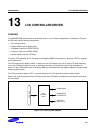
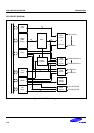

S3C9228/P9228 LCD CONTROLLER/DRIVER
13-5
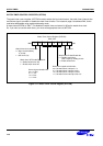
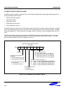
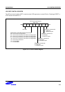
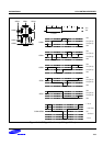
LCD PORT CONTROL REGISTER
The LCD port control register LPOT is used to control LCD signal pins or normal I/O pins. Following a RESET, a
LPOT values are cleared to "0".
LCD Port Control Register
D8H, R/W
.7 .6 .5 .4 .3 .2 .1 .0MSB LSB
Not used
SEG0/P2.1 selection bit:
0 = SEG port
1 = Normal I/O port
SEG4-SEG19 and COM0-COM3 selection bits:
000 = P4.0-P6.3: LCD signal pins
001 = P4.0-P4.3: Normal I/O, P4.4-P6.3: LCD signal pins
010 = P4.0-P4.7: Normal I/O, P5.0-P6.3: LCD signal pins
011 = P4.0-P5.3: Normal I/O, P5.4-P6.3: LCD signal pins
100 = P4.0-P5.7: Normal I/O, P6.0-P6.3: LCD signal pins
101 = P4.0-P6.3: Normal I/O
110 = Not available
111 = Not available
SEG1/P2.0 selection bit:
0 = SEG port
1 = Normal I/O port
SEG2/P3.1 selection bit:
0 = SEG port
1 = Normal I/O port
SEG3/P3.0 selection bit:
0 = SEG port
1 = Normal I/O port
Figure 13-5. LCD Port Control Register