


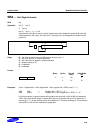
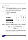
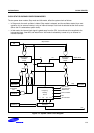
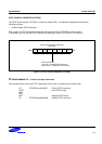
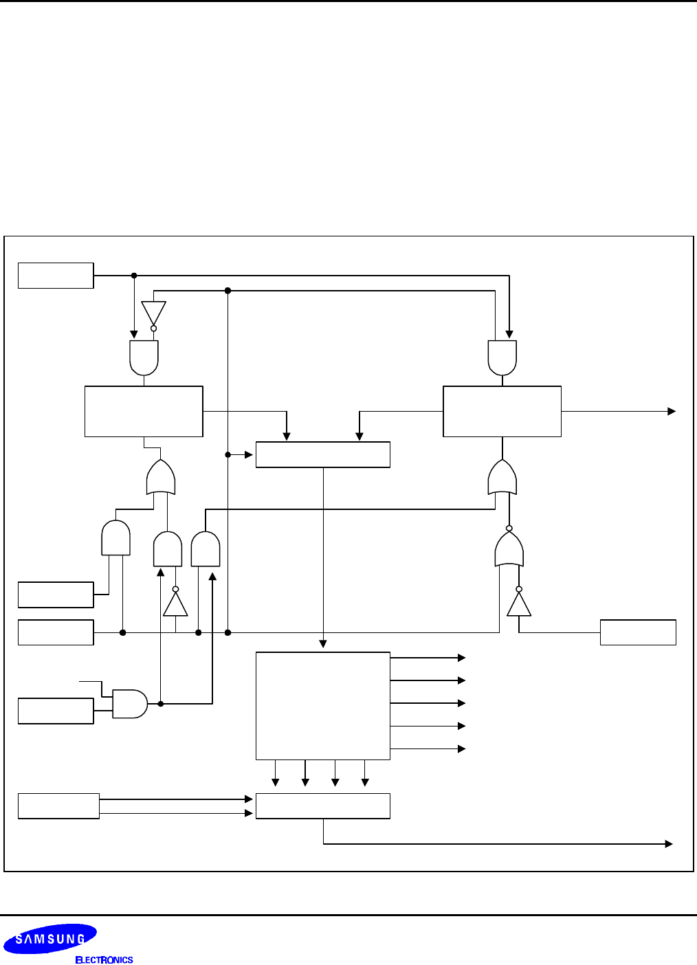
S3C9228/P9228 CLOCK CIRCUITS
7-3
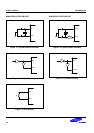
CLOCK STATUS DURING POWER-DOWN MODES
The two power-down modes, Stop mode and Idle mode, affect the system clock as follows:
— In Stop mode, the main oscillator is halted. Stop mode is released, and the oscillator started, by a reset
operation, by an external interrupt, or by an internal interrupt if sub clock is selected as the clock source
(When the fx is selected as system clock).
— In Idle mode, the internal clock signal is gated away from the CPU, but continues to be supplied to the
interrupt structure, timer A/B, and watch timer. Idle mode is released by a reset or by an external or
internal interrupts.
1/8-1/4096
Frequency
Dividing
Circuit
Stop Release
Main-System
Oscillator
Circuit
Selector 1
f
X
f
XT
Stop
Sub-system
Oscillator
Circuit
INT
OSCCON.0
OSCCON.3
OSCCON.2
1/1 1/161/2 1/8
Selector 2
STPCON
STOP OSC
inst.
f
XX
CLKCON.4-.3
CPU
Stop
Watch Timer
Basic Timer
Timer/Counters
Watch Timer
LCD Controller
A/D Converter
SIO
LCD Controller
Figure 7-6. System Clock Circuit Diagram