


S3C9228/P9228 LCD CONTROLLER/DRIVER
13-1
13 LCD CONTROLLER/DRIVER
OVERVIEW
The S3C9228/P9228 microcontroller can directly drive an up-to-128-dot (16segments x 8 commons) LCD panel.
Its LCD block has the following components:
— LCD controller/driver
— Display RAM for storing display data
— 16 segment output pins (SEG0–SEG15)
— 8 common output pins (COM0–COM7)
— Internal resistor circuit for LCD bias
To use the LCD controller, bit 2 in the watch mode register WMOD must be set to 1 because LCDCK is supplied
by the watch timer.
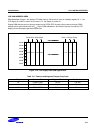
The LCD mode control register, LMOD, is used to turn the LCD display on or off, to select LCD clock frequency,
to turn the COM signal output on or off, to select bias and duty, and to switch the port 3 high impedance or
normal I/O port. Data written to the LCD display RAM can be transferred to the segment signal pins automatically
without program control.
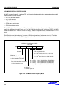
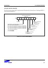
The LCD port control register, LPOT, is used to determine the LCD signal pins used for display output.
When a sub clock is selected as the LCD clock source, the LCD display is enabled even during main clock stop
and idle modes.
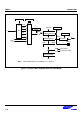
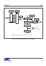
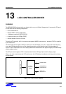
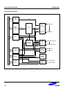
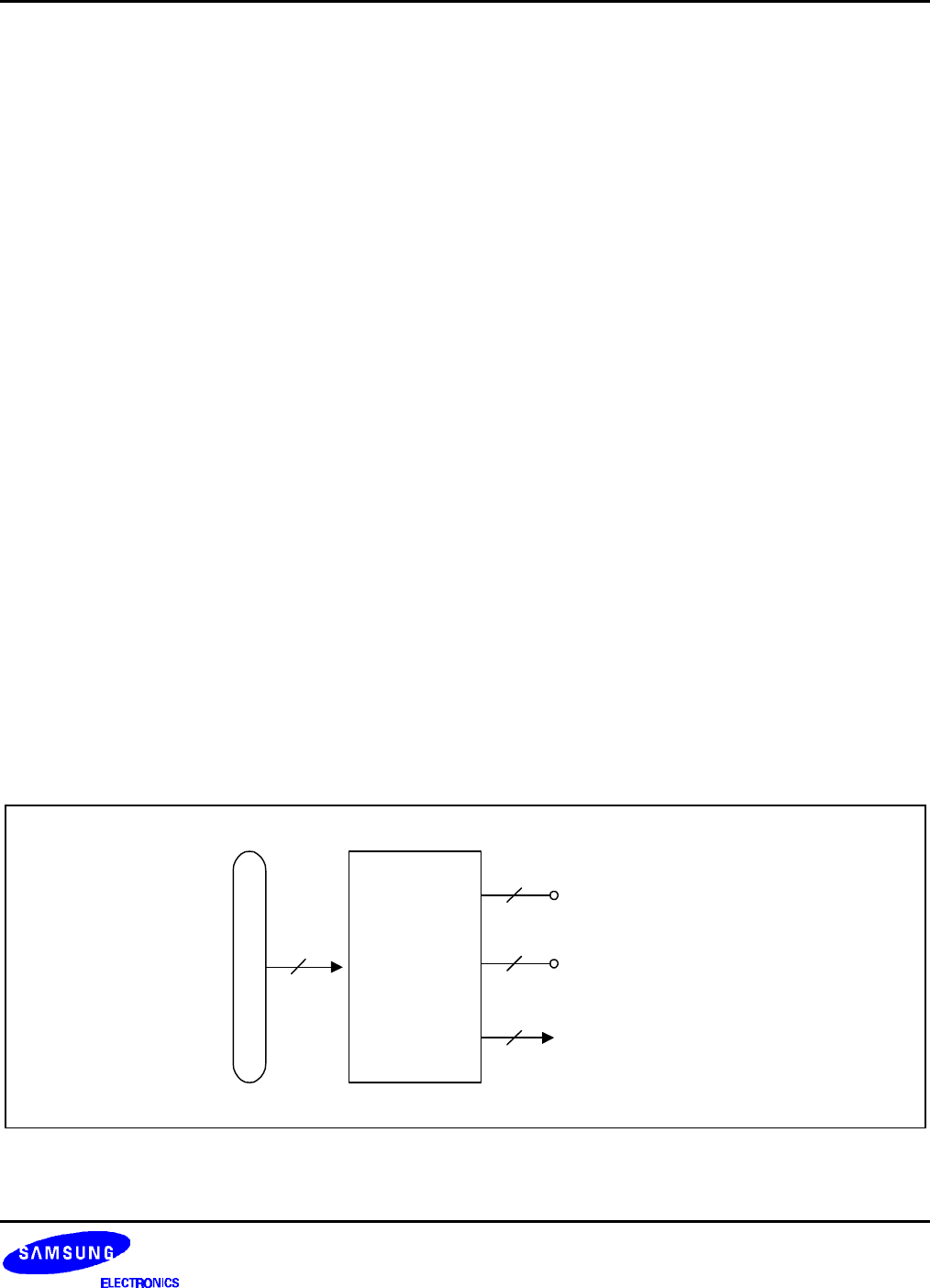
LCD
Controller/
Driver
COM0-COM3
SEG0/P2.1-
SEG15/P5.3
16
4
8
Data BUS
COM4/SEG19-
COM7/SEG16
4
Figure 13-1. LCD Function Diagram