


S3C9228/P9228 INTERRUPT STRUCTURE
5-1
5 INTERRUPT STRUCTURE
OVERVIEW
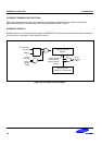
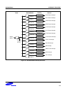
The SAM88RCRI interrupt structure has two basic components: a vector, and sources. The number of interrupt
sources can be serviced through a interrupt vector which is assigned in ROM address 0000H–0001H.
SOURCESVECTOR
S1
S2
S3
Sn
0000H
0001H
NOTES:
1. The SAM88RCRI interrupt has only one vector address (0000H-0001H).
2. The number of Sn value is expandable.
Figure 5-1. S3C9-Series Interrupt Type
INTERRUPT PROCESSING CONTROL POINTS
Interrupt processing can be controlled in two ways: globally, or by specific interrupt level and source. The system-
level control points in the interrupt structure are therefore:
— Global interrupt enable and disable (by EI and DI instructions)
— Interrupt source enable and disable settings in the corresponding peripheral control register(s)
ENABLE/DISABLE INTERRUPT INSTRUCTIONS (EI, DI)
The system mode register, SYM (DFH), is used to enable and disable interrupt processing.
SYM.3 is the enable and disable bit for global interrupt processing, which you can set by modifying SYM.3. An
Enable Interrupt (EI) instruction must be included in the initialization routine that follows a reset operation in order
to enable interrupt processing. Although you can manipulate SYM.3 directly to enable and disable interrupts
during normal operation, we recommend that you use the EI and DI instructions for this purpose.