


Introduction
12
890USE19600 April 2004
Structural
Overview
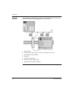
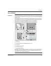
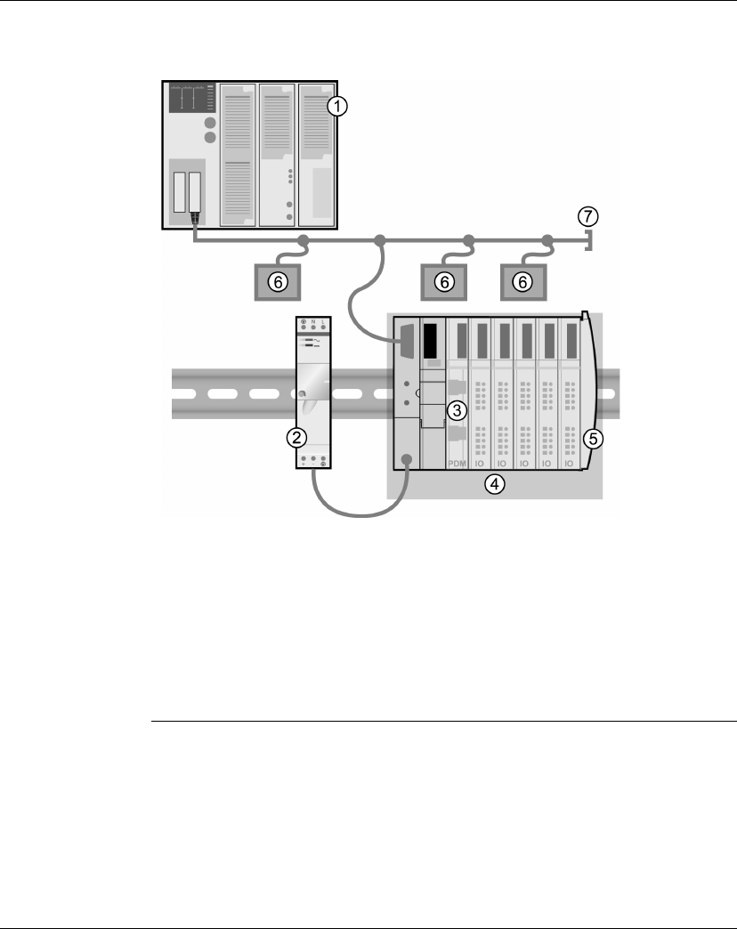
The following figure illustrates the multiple roles of the NIM. The figure provides a
network view and a physical representation of the island bus:
1 fieldbus master
2 external 24 VDC power supply, the source for logic power on the island
3 power distribution module (PDM)
4 island node
5 island bus terminator plate
6 other nodes on the fieldbus network
7 fieldbus network terminator (if required)