


The STB NIB 1010 Basic NIM Module
18
890USE19600 April 2004
External Features of the STB NIB 1010 NIM
Hardware
Features
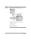
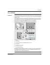
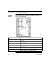
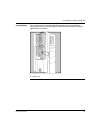
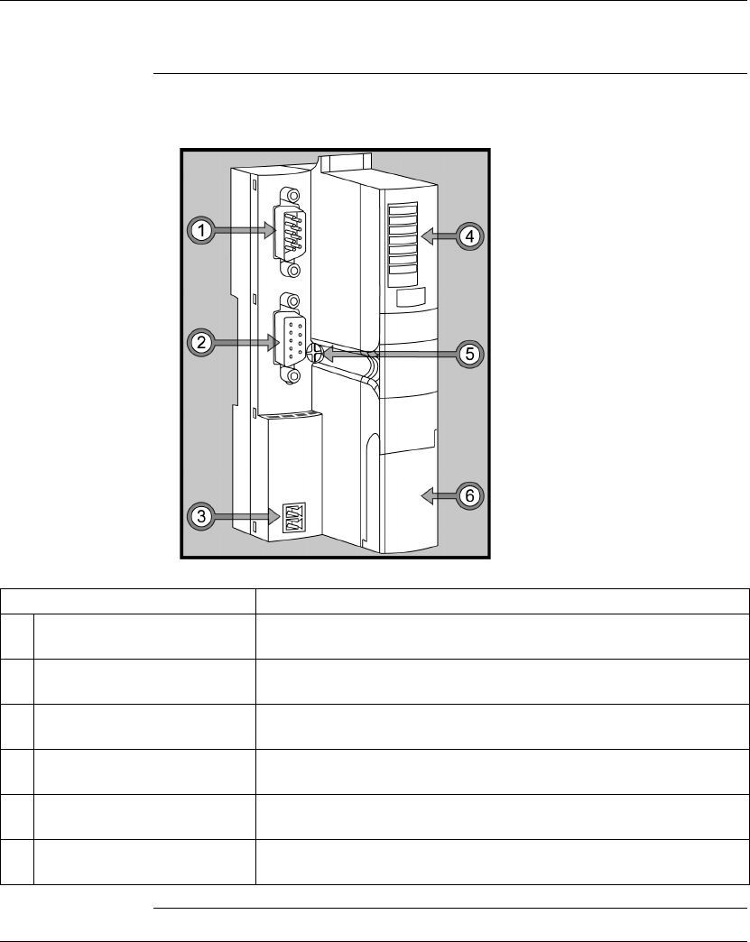
The physical features critical to STB NIB 1010 INTERBUS NIM operations are
called out in the illustration below:
Feature Function
1 fieldbus interface (in) Nine-pin SUB-D (male) connector used for the incoming INTERBUS fieldbus
network cable.
2 fieldbus interface (out) Nine-pin SUB-D (female) connector used for the outgoing INTERBUS
fieldbus network cable.
3 power supply interface A two-receptacle connector for connecting an external 24 VDC power supply
to the NIM.
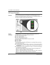
4 LED array Colored LEDs that use various patterns to visually indicate the operational
status of the island bus.
5 release screw A mechanism used to remove the NIM from the DIN rail. (See the Advantys
STB System Planning and Installation Guide for details.)
6 CFG port cover A hinged flap on the NIM’s front panel that covers the CFG interface and the
RST button. The CFG port is for firmware upgrades only.