


The STB NIB 1010 Basic NIM Module
22
890USE19600 April 2004
LED Physical Description
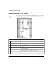
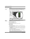
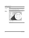
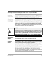
Overview The six LEDs implemented in the STB NIB 1010 INTERBUS NIM are visual
indications of the operating status of the island bus on an INTERBUS network. The
LED array is located at the top of the NIM front bezel.
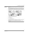
General
Indications
The bottom three LEDs indicate the status of data exchange between the
INTERBUS fieldbus master and the Advantys island bus:
LED 4—RC (remote bus check)
LED 5—BA (bus active)
LED 6—RD (remote bus disabled)
The top three LEDs indicate activity or events on the NIM:
LED 1—RUN
LED 2—PWR/UL
LED 3—ERR
The following tables describe the LED behavior in more detail. When you refer to
these tables, keep in mind:
It is assumed that the PWR/UL LED is on continuously, indicating that the NIM is
receiving adequate power. If the PWR/UL LED is off, logic power to the NIM is off
or insufficient.
Individual blinks are approximately 200 ms. There is a 1-second interval between
blink sequences. For example:
blinking—blinks steadily, alternating between 200 ms on and 200 ms off
blink 1—blinks once (200 ms), then 1 second off
blink 2—blinks twice (200 ms on, 200 ms off, 200 ms on), then 1 second off
blink n—blinks n (some number) times, then 1 second off