


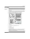

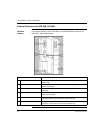
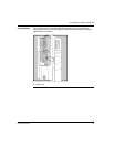
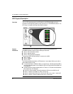
The STB NIB 1010 Basic NIM Module
890USE19600 April 2004 21
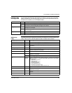
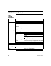
The pin-out for both the in (upper) and out (lower) connectors should be according
to the table below (pin numbers correspond to callouts in the figure above):
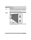
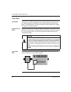
INTERBUS
Networking
Cable and
Connectors
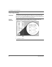
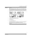
The drop cable from the fieldbus to the Advantys STB INTERBUS NIM (and the one
from the NIM to the next INTERBUS node) must have connectors that observe this
pin assignment scheme. INTERBUS networking cables are shielded, twisted-pair
electrical cables, compliant with INTERBUS standard DR-303-1. There should not
be an interruption to any wire in bus cables. This allows for a future specification for
use of reserved pins.
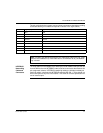
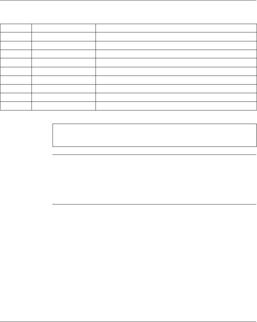
Pin Signal (in) Signal (out)
1DO1 DO2
2DI1 DI2
3 GND1 GND
4 unused unused
5 unused +5 V
6/DO1 /DO2
7/DI1 /DI2
8 unused unused
9 unused RBST (see note below)
Note: The RBST pin detects the presence of a subsequent node on the ring. In the
absence of this detection (or if the node has no out connector at all), the network
ring is closed.