


Introduction
14
890USE19600 April 2004
Physical Layer The physical layer contains a single twisted pair of shielded wires. The
STB NIB 1010 INTERBUS implements the SUPI 3 (serial universal peripheral
interface) ASIC from Phoenix Contact.
Network
Topology
The INTERBUS network observes a master/slave model with active ring topology,
having all devices integrated in a closed transmission path. There are three types of
bus structures in the ring:
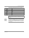
remote bus—The Advantys STB island (with an STB NIB 1010 INTERBUS NIM
at the head) connects to this section. Remote bus characteristics include:
12.8 km (maximum) network length
512 possible connections
400 m (maximum) between devices
256 devices (maximum)
local bus (not supported)—The local bus ring is used to connect I/O devices in a
remote substation enclosure. Local bus characteristics include:
8 devices (maximum)
1.5 m (maximum) between devices
10 m (maximum) network length
800 mA (maximum) current
sensor loop—The sensor loop is connected directly to sensors and actuators
without the use of bridge routers. Sensor loop characteristics include:
1 unshielded pair (+24 V)
32 devices (maximum)
10 m (maximum) network length
Transmission
Media
While it is possible to connect INTERBUS devices with a variety of media (fiber
optics, SMG, etc.), the STB NIB 1010 NIM only supports networks that are
connected with twisted pair copper wiring (RS-485). Network connectors (in and out)
are 9-pin SUB-D types. The TDMA transmission method is implemented for
transmission rates of 500 kbits/s.
Note: An Advantys STB island with an INTERBUS NIM head can be implemented
only as a remote bus node.