


Fieldbus Communications Support
40
890USE19600 April 2004
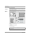
Input and Output
Data Exchange
The application of the INTERBUS bit packing rules to the sample island assembly
results in four words of output data and five words of input data. The tables that
follow show how digital data is bit packed for optimization, and how data, status, and
echo output data (from outputs) appear in the PLC as the same data type (digital
input data). In these tables, N refers to the island node number. That is, N1
represents the first addressable node (module) on the sample island bus, N2 the
second, and so forth.
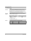
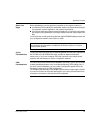
Output Data
Exchange
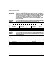
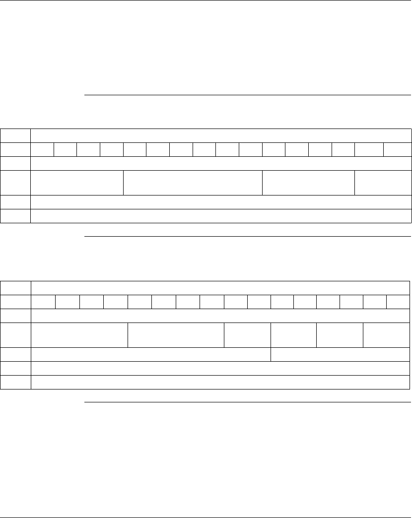
The following table shows how the four words in the sample island assembly output
data process image are organized after applying the bit packing rules:
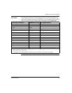
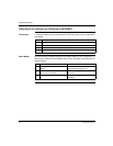
Input Data
Exchange
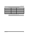
The following table shows how the five words of the sample island assembly output
data process image are organized after applying the bit packing rules. The first word
contains the NIM status.
Bit Number
Word 15 14 13 12 11 10 9 8 7 6 5 4 3 2 1 0
1 NIM control word
2 empty (set to 0) N6 output data N4 output data N2 output
data
3 N8 (channel 1) analog output data
4 N8 (channel 2) analog output data
Bit Number
Word 15 14 13 12 11 10 9 8 7 6 5 4 3 2 1 0
1 NIM status
2 empty (set to 0) N3 input data N2 output
status
N2 output
echo
N1 input
status
N1 input
data
3 empty (set to 0) N5 input data
4 N7 (channel 1) analog input data
5 N7 (channel 2) analog input data