


Fieldbus Communications Support
890USE19600 April 2004 39
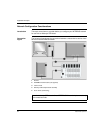
The Internal
Process Image
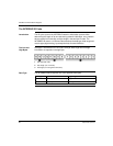
The STB NIB 1010’s process image contains memory areas (buffers) for the
temporary storage of input and output data. The internal process image is part of the
NIM’s island bus scanner area.
The island bus manages data exchange in both directions:
input data from the island bus—The island bus scanner operates continuously,
gathering data as well as status and confirmation bits and putting them into the
process image’s input buffer.
output data to the island bus—The island bus scanner handles output data and
places it in the process image’s output buffer.
Input data and output data are assembled in the order of the island bus I/O modules
(from left to right).
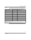
Word
Boundaries and
Bit Packing
Every entry in the process image is in a multiple-word format. If modules on the
island bus have input or output data entries that are not multiple words, the
corresponding word in the process image is moved to the next word boundary.
For example, a module with one bit of output data starts on a word boundary in the
process image’s output data buffer. The next process image entry starts on the next
word boundary, thereby transmitting 15 unused bits of the module’s first word,
resulting in latency during data transmission on the fieldbus.
Bit packing allows bits of data on the fieldbus from different digital I/O modules to be
put together in a single byte, resulting in optimized bandwidth.
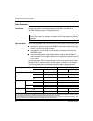
Bit Packing
Rules
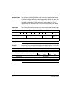
The STB NIB 1010 NIM observes the following rules for the bit packing of the
external process image:
The input and output process image sizes are limited to 16 words each.
The first word of the input process image contains NIM status information. The
first word of the output process image contains the NIM control word.
Bit packing follows the addressing order of the island bus I/O modules, from left
to right in the basic segment.
When the data object (or echo output data object) for a specific module is
available, it precedes the status object for that module.
Status objects and data objects for the same or different I/O module may be
packed in the same word if the size of the combined objects is 16 bits or less.
If the combination of objects requires more than 16 bits, the objects will be placed
in separate contiguous bytes. A single object cannot be split over two
word boundaries.
For standard analog input modules, channel 1 data is followed immediately by
channel 1 status, then channel 2 data and channel 2 status.