


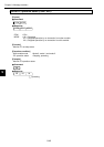
10-1
Chapter 10: Communication Control
10
Chapter 10: Communication Control
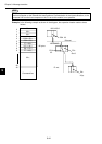
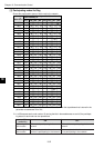
A participating node list flag, an operation status flag, error status flag, local node management table,
participating nodes management table, and network management table are set up in the communica-
tion control area of the JW-50FL.
(Complete setting procedure for the JW-50FL => See page 8-3.)
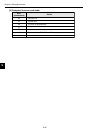
* Addresses +000 to 301(8) are offset addresses calculated from the top address of the communica-
tion control area. Enter the top address for the communication control area as a parameter at
addresses 30 to 32(8)).
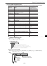
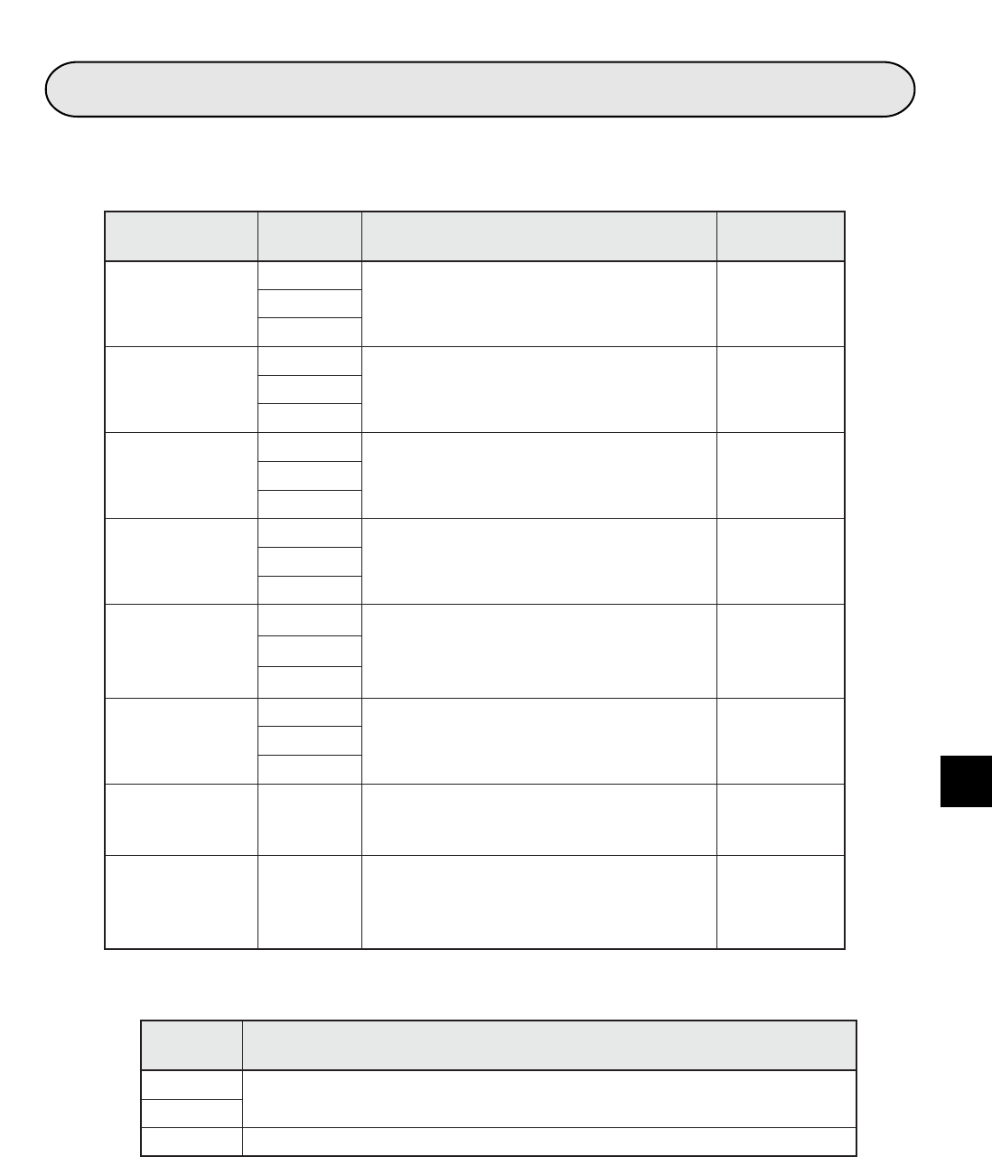
Communication
control area
Address
(8)
*
Control details
Reference
section
Participating
nodes list flag
+000
Participating status of each node in the
network
[1]to
+037
Operation status
flag
+040
Operation information for each node [2]to
+077
Error status flag
+100
Error information of each node [3]to
+137
Local node
management
table
+140
Information concerning own node [4]to
+233
Participating
node
management
table
+234
Node number information written to the
base address +300
[5]to
+253
Network
management
table
+254
Information common to the network [6]to
+267
Node number to
read information
+300
Node number to read information to the
participating node management table
(address +234 to 253)
---
Transmit the data +301
Write 01
(H)
is written to this address, the
data in the transmission area [information
and data sections] of the transmission
buffer is sent to the target node.
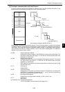
---
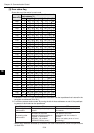
Parameter
address
(8)
Details
30
Top address (word address) of the communication control area in the PC.
- Address 30 is for the lower digit. Address 31 is for the upper digit.
31
32 File number of the communication control area in a PC.
(Parameter => See Chapter 12)