


5-1
Chapter 5: Installation
5
Chapter 5: Installation
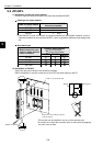
5-1 Installation of JW-20FL5/20FLT
This section describes the installation procedures for the JW-20FL5/20FLT (hereafter referred to as the
module) on the JW20H/30H basic rack panel.
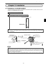
Turn off the power to the JW20H/30H.
Set the module No. switch on the back of the module.
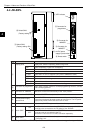
Insert the mounting rib on the module into the rib insert holes on the JW20H/30H basic rack panel
and push in. Then, tighten module-mounting screws at the top of the module using a Phillips-head
(+) screwdriver.
Notes
- The module cannot be installed into an expansion rack panel.
- More than two communication modules can be installed on the same control module (basic rack panel
for the JW20H/30H). However, be careful not to use the same module No. switch setting for any other
module (including JW-20FL5/20FLT).
- Make sure to tighten the module mounting screws securely. Loose screws may cause a malfunction.
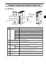
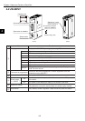
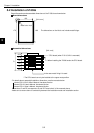
(Back of the communication module)
Module No. switch
Module rib
insert hole
Module rib
Intermediate plate
or control panel
Basic rack panel
Module insert guide
This module
Ventilation hole
Module mounting screw
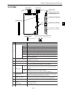
Basic rack panel
The module
(The figure shows a JW-20FL5.)
Control module
JW-21CU/22CU, JW-31CUH1/32CUH1
JW-33CUH1/33CUH2/33CUH3
Phillips-head
screwdriver
(Installation example)
Power supply module