


9-17
Chapter 9: Message transfers
9
Command
page 9-
14.
Transmission
buffer address
(8)
Details
+2000
Header (40 bytes)
- Normally, all 40 bytes to 00
(H)
.
When you want to communicate crossover
two layers including Ethernet, enter
expansion header.
- [5] Two layer communication with Ethernet.
Sending
[data section]
to
+2047
+2050 c-ID: 47
(H)
+2051 ATTR: 00
(H)
+2052 COM: Command code - Page 9-14.
+2053
Command Text: Command detail
- [3] Description of each command
to
+3777
+4040 Node number of destination node.
Sending
[information section]
+4041 00
(H)
(Response message type)
+4042 to 4043 1000
(H)
(Transaction code: request)
+4044 to 4047
00
(H)
(Top address of the virtual address
space)
+4050 to 4051
00
(H)
(Data length requesting to the virtual
address space)
+4052 01
(H)
(Current fragment block number)
+4053 01
(H)
(Total fragment block number)
+4054 to 4055 00
(H)
(Current block length)
Communication control
area address
(8)
Details
+301 Transfer the data
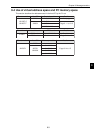
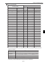
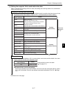
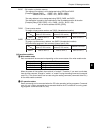
[1] Setting the computer link to send and receive data
When a computer link message format is used, the sending and receiving details of the transmission
buffer are set as follows.
11
11
1 Setting the sending details (command)
Put the address of the [information section] and [data section] containing the data to be sent in the
transmission buffer (base address +2000 to 3777(8), and base address +4040 to 4055(8)).
(Transmission buffer table Page 9-4.)
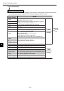
22
22
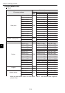
2 Transmit the data
Write 01(H) at the base address +301 in communication control area and the details in the trans-
mission buffer will be sent to the destination node.
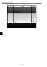
Communication control area settings
Enter the top address of the communication control area and the area (base address +000 to
301(8)) will be allocated. Enter the top address at parameter addresses 30 to 32(8). Page
12-1.
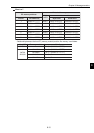
Continued on the next page.
(Communication control area table
See page 10-1.)