


10-5
Chapter 10: Communication Control
10
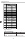
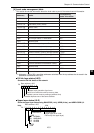
[4] Local node management table
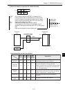
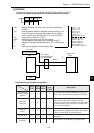
This section shows the information about the local node as part of the network control information.
*1: Addresses +140 to 223(8) are offset addresses calculated from the top address that is stored in the
parameter at addresses 30 to 32(8).
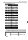
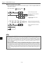
FA link layer status (LKS)
Shows the FA link status of the network.
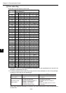
Upper layer status (ULS)
Show the upper layer status using RUN/STOP (1 bit), UERR (2 bits), and UERR CODE (12
bits).
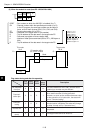
Address
(8)
Details
Corresponding
header information
+140 Node number
+141 Reserved area
+142 to 153 Node name (facility name)
+154 to 165 Vendor name
+166 to 177 Manufacturer's model name
+200 This node's status
+201 Reserved area
+202 FA link layer status => See below LKS
+203 Reserved area
+204 to 205 Status of the upper layer => See below ULS
+206 to 207 Common memory (area 1) storage address C_AD1
+210 to 211 Common memory (area 1) storage size C_SZ1
+212 to 213 Common memory (area 2) storage address C_AD2
+214 to 215 Common memory (area 2) storage size C_SZ2
+216 Token monitor time-out time TW
+217 Reserved area
+220 Minimum allowable time between frames MFT
+221 Reserved area
+222 Protocol version PVER
+223 Reserved area
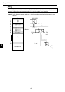
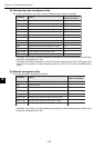
76543210
Spare
Bit
Upper layer operation signal error
Notice to be effective common memory data
Complete common memory settings (address size)
Detected duplicate use of the same address
Base address +202
Reserved bit
U ERR
U ERR CODE
(Upper layer error code:
Defined by the upper layer)
+204
00 NORMAL
01 WARNING
10 ALARM
11 ALARM
0 STOP
1 RUN
7654321076543210
Bit
Base address +205