


10-6
Chapter 10: Communication Control
10
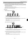
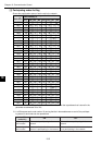
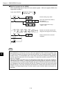
[5] Participating node management table
Shows the information for the node numbers at address offset +300 for each table.
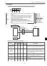
- Addresses +224 to 253(8) are offset addresses calculated from the top address that is stored in the
parameter at addresses 30 to 32(8).
- The details of the offset addresses at +234 (FA link layer status) and at +236 to 237 (upper layer
status) are the same as for offset addresses +202 and +204 to 205 in the Local Node Control
Table.
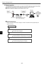
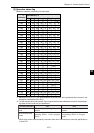
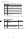
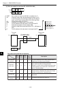
[6] Network management table
Shows the information shared by the network.
- Addresses +254 to 267(8) are offset addresses calculated from the top address that is stored in the
parameter at addresses 30 to 32(8).
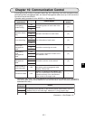
Address
(8)
Details
Corresponding
header information
+224 to 225 Common memory (area 1) storage address C_AD1
+226 to 227 Common memory (area 1) storage size C_SZ1
+230 to 231 Common memory (area 2) storage address C_AD2
+232 to 233 Common memory (area 2) storage size C_SZ2
+234 FA link layer status LKS
+235 Reserved area
+236 to 237 Upper layer status ULS
+240 Token monitor timeout time TW
+241 Reserved area
+242 Minimum allowable time between frames MTF
+243 Reserved area
+244 to 245 Time allowed for the refresh cycle RCT
+246 to 253 Reserved
Address
(8)
Details
Corresponding
header information
+254 Token holding the node number
+255 Reserved area
+256 Minimum allowable time between frames MFT
+257 Reserved area
+260 to 261 Refresh cycle measured time (calculated value)
+262 to 263 Refresh cycle measured time (current value)
+264 to 265 Refresh cycle measured time (max. value)
+266 to 267 Refresh cycle measured time (min. value)