


12-4
Chapter 12: Parameters
12
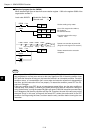
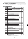
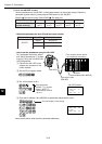
Switch SW3 setting 0 1 2 3 4
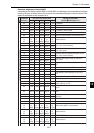
Parameter address
(8)
(system memory)
#0300 to
#0377
#1400 to
#1477
#1500 to
#1577
#1600 to
#1677
#1700 to
#1777
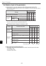
Connection cable
(ZW-3KC)
JW-14PG
Control module (JW-100CUH)
JW-50FL
(The modules shown below
are installation examples)
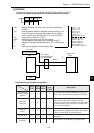
FL-net module Host PC Control module
JW-50FL
JW50H JW-50CUH
JW70H JW-70CUH
JW100H JW-100CUH
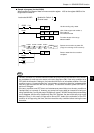
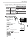
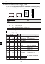
Read parameter
address 77
(8)
(system
memory #0377 *).
* When switch SW3 is
set to 0.
Decimal display of the setting
#0301 DCM 168
#0302 DCM 250
P System
>#0303 DCM 003
#0375 HEX 00
#0376 HEX 00
P System
>#0377 HEX 00
JW-14PG screen
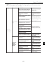
[2] When the JW-50FL is used
Set the parameters for the JW-50FL in the system memory of the control module. Select the
parameter (system memory) area using the SW3 switch on the JW-50FL.
(Details See the next page. Switch SW3 See page 4-4.)
Note: Do not set switch SW3 outside the range of 0 to 4.
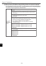
- Relationship between the host PC and the control module
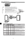
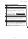
- How to set the parameters using the JW-14PG
This paragraph describes param-
eter setting procedures (in system
memory) using the handheld JW-
14PG programmer.
1 Connect the JW-14PG to the
support tool connector on the
control module.
2 Set the PC to program mode.
3 Set a start switch to 00(H).
4 Enter the IP address (192.168.250.3) at parameter addresses 00 to 03(8).
Same as the above, enter the other parameter addresses.