


9-4
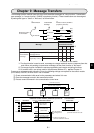
Chapter 9: Message transfers
9
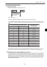
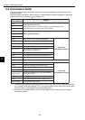
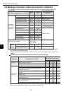
9-2 Transmission buffer
This section describes the transmission buffer that is used for sending and receiving data for the
message transfer.
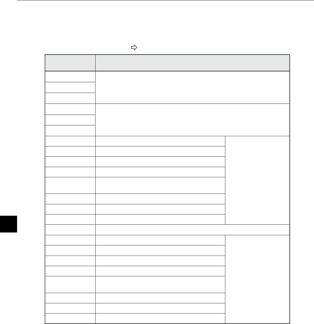
The transmission buffer area (+0000 to 4055(8)) is determined by entering top address to parameter
(address 34 to 36(8)). (Parameter See Chapter 12.)
*1: The data in the transmission area [information section] and [data section] are transferred when
01(H) is written at the base address +301 in the communication control area. After sending data,
JW-50FL clears the setting data of the sending data section.
*2: Enter 255(D) at the base address +4040. Then the data will be transferred to all the nodes
currently connected.
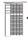
Transmission
buffer address
(8)
Details
+0000
Receiving [data section]
- When writing 00
(H)
to address +4000, the received data will be
transferred to the control module (CPU board)
to
+1777
+2000
Sending [data section] *
1
to
+3777
+4000 Node number of the node sending data.
Receiving
[information section]
+4001 Response message type (always 00
(H)
)
+4002 to 4003 Transaction code (response).
+4004 to 4007 Top address of the virtual address space.
+4010 to 4011
Data length of response from the virtual
address space (word/byte).
+4012 Current fragment block number (always 01
(H)
)
+4013 Total fragment block number (always 01
(H)
)
+4014 to 4015 Current block length (byte)
+4016 to 4037 Reserved area
+4040 Node number of destination node. *
2
*1 Sending
[information section]
+4041 Response message type (always 00
(H)
)
+4042 to 4043 Transaction code (request).
+4044 to 4047 Top address of the virtual address space.
+4050 to 4051
Data length requesting to the virtual address
space (word/byte).
+4052 Current fragment block number (always 01
(H)
)
+4053 Total fragment block number (always 01
(H)
)
+4054 to 4055 Current block length (byte)