


15-26
Chapter 15: Appendix
15
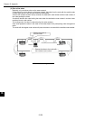
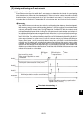
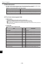
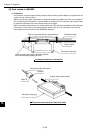
[3] Node status control
The status control of nodes consists of a local node management table, a participating nodes manage-
ment table, and a network management table. An outline of each is shown below.
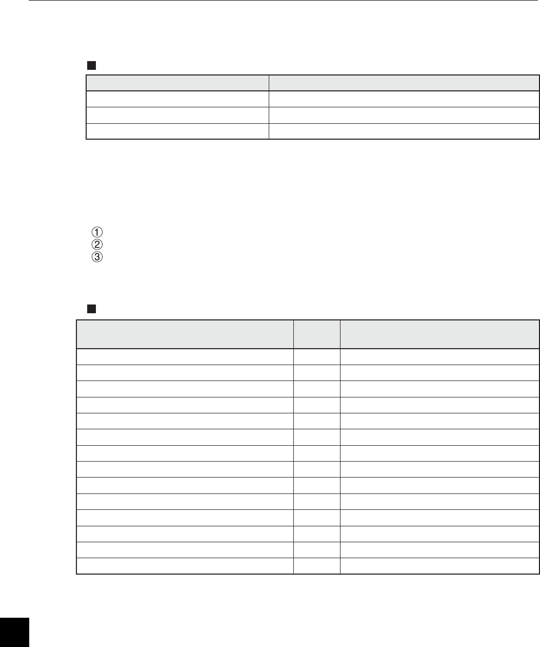
Outline of each table used for node status control
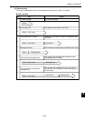
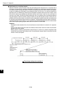
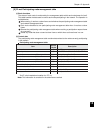
[4] FL-net Local node management table
(1) Basic function
Control data relating to this node. An outline is shown below.
Used for reading participating request frames and network parameters.
The control data are set by the FL-net upper layer when this node starts.
The node name, top address and size of the data send area in the common memory can be set
through the network.
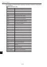
(2) Control data
Individual node management table
Item
Number
of bytes
Description
Node number 1 byte 1 to 254
Area 1 of common memory: Data top address 2 bytes Word address (0 to 0x1ff)
Area 1 of common memory: Data size 2 bytes Size (0 to 0x1ff)
Area 2 of common memory: Data top address 2 bytes Word address (0 to 0x1fff)
Area 2 of common memory: Data size 2 bytes Size (0 to 0x1fff)
Upper layer status 2 bytes RUN/STOP/ALARM/WARNING/NORMAL
Token monitor time 1 byte In units of 1 msec.
Minimum separation of frames 1 byte In units of 100 µsec.
Vendor name 10 bytes Vender name
Manufacturer name 10 bytes Manufacture model name, device name
Node name (facility name) 10 bytes Node name by user entry
Protocol version 1 byte Fixed to 0x80
FA link status 1 byte Participate/leave
Local node's status 1 byte Doubled node number detection, etc.
Name Details
Local node management table Control its own node settings.
Participating nodes management table Control information about nodes participating the network.
Network management table Control information shared throughout the network.