


9-1
Chapter 9: Message transfers
9
*1
Client function
Use
Do not use
Use
Do not use
Use
Do not use
Use
Do not use
Use
Do not use
81
(H)
83
(H)
81
(H)
80
(H)
82
(H)
00
(H)
Message transfer
of the module
Transmission
message
*2
Remote function (SHARP’s
proprietary function)
Send data (request)
Receive data (response)
Address(8)
30
33
34
37
77
Parameter
Transmission buffer
Address(8)
0000
1777
2000
3777
4000
4015
4040
4050
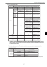
Inside the control module (CPU board) of the PC
Start switch
000
301
Communication
control area
*1
- Parameters => See Chapter 12
*2
This node
(Host PC
for the
module)
Node
used to
exchange
data
Set up the communication
control area
Set up a transmission
buffer
Received data
(data section)
Transmitted data
(data section)
Received data
(information section)
Transmitted data
(information section)
Enter the details for
the messages to be
sent
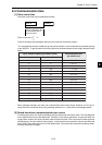
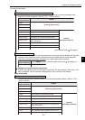
*1: Enter the top address at
parameter addresses 34 to 36.
Execute a send
data command
*2: Enter the top address at
parameter addresses 30 to 32.
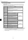
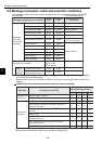
Message
Selection of
transmission buffer
80
(H)
81
(H)
82
(H)
83
(H)
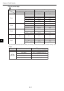
Message other than transmission
Transmission
message
Messages other than SHARP's proprietary
message format
SHARP's
proprietary format
Computer link function
Remote function
*3
Chapter 9: Message Transfers
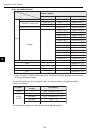
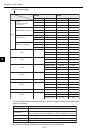
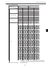
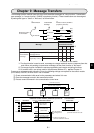
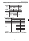
The message transfer method used with the module classifies messages as "client function," "transmission
type message," or "remote function" (SHARP's proprietary function). These classifications can be assigned
by setting each type to "Used" or "Not used," as shown below.
O: Usable X: Not usable
*1: The client function is used to send a message to a target node and receive a response from that
node. When not sending a transmission message, set the client function to "Not used."
*2: The remote function includes the remote programming and remote monitoring functions.
*3: 00, and 80 to 83(H) are values used for the parameter address 37(8). See Chapter 12.
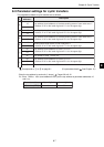
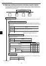
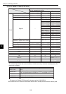
To execute a message transfer using the FL-net, the following settings are required on the control module
(CPU board) of the PC on which the FL-net is installed.
1 Create a transmission buffer area for the parameters and select it for use.
2 Place the message to send in the transmission buffer.
3 Execute a send command in the communication control area.