


15-60
Chapter 15: Appendix
15
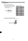
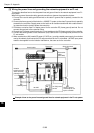
[3] Wiring the power lines and grounding the network equipment in an FL-net
This section describes how to wire the power lines and ground lines for the network equipment in an FL-
net system.
When wiring power lines and making ground connections, observe the precautions below.
1. Connect the coaxial cable ground terminal to the class D ground that is specially created for the
controller.
2. Connect the frame ground of the hubs for a 10BASE-T system to the class D ground that is specially
created for the controller. Supply power to the hub from an isolation transformer with a static electric-
ity protective function (used to power the controller).
3. Provide an exclusive class D or better ground for the controller FG (frame ground) terminal. Do not
connect this terminal to the controller frame.
4. Connect the FG (frame ground) terminal of FL-net modules to the FG (frame ground) of the controller.
5. Connect the shield ground on the transceiver (AUI) cable to the FG (frame ground) terminal on the
FL-net module.
6. When a transceiver (AUI) needs DC power (12 VDC etc.), provide a stable power supply for exclusive
use by the network, and connect the DC output terminals to the FL-net module. 100 VAC input power
needs to be supplied from the isolation transformer, the same as for the controller.
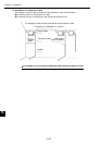
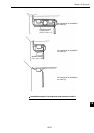
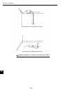
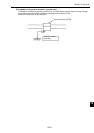
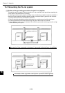
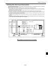
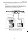
Example of how to wire power lines and ground lines for network equipment in the FL-net system
Coaxial cable
Transceiver Ground terminal
Hub
Transceiver
cable
(AUI cable)
Isolation
transformer with
static electricity
protective function
100 VAC
Class D ground
100 VAC
12 VDC power
for AUI
Class D ground
exclusively for use
by the controller