


4-4
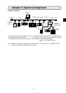
Chapter 4: Name and Function of Each Part
4
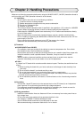
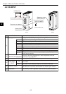
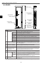
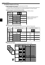
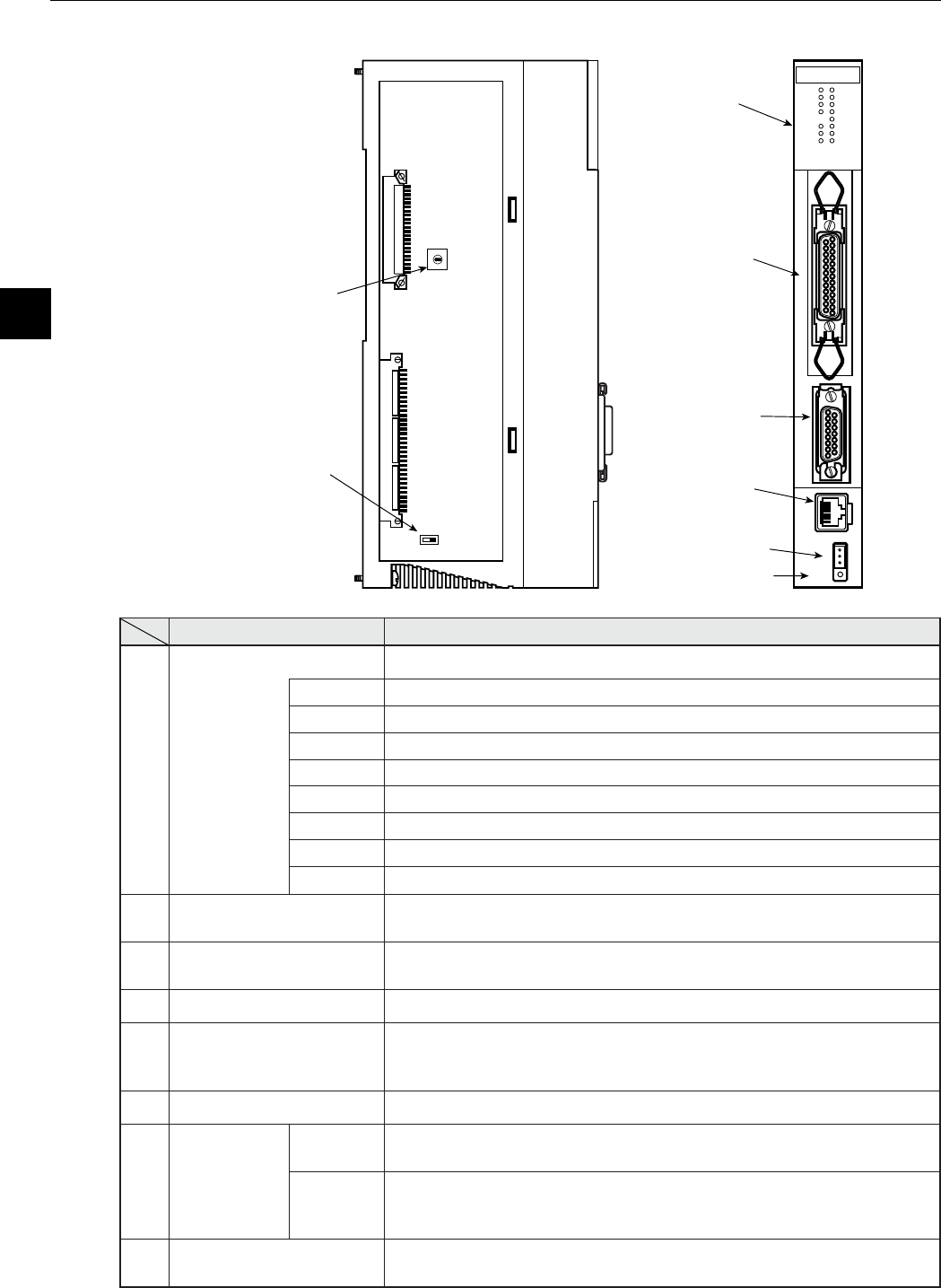
4-4 JW-50FL
Note: Only 10BASE5 or 10BASE-T protocol is used. Mixed use of these two types is not permitted.
JW-50FL
S0
S1
S2
S3
S4
S5
S6
S7
LNK
TX
RX
DC12V
TEST
PER
HER
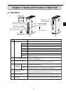
1 LED indicator
6 Reset switch
2 Connector for
programmer
3 Connector for
10BASE5
5 12 VDC power
supply input terminal
8 Switch SW3
(Factory setting: 0)
7 Switch SW3
(Factory setting: ON)
4 Connector for
10BASE-T
Name Function
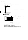
1
Display panel Displays the JW-50FL operating status using LEDs.
LNK Lights at operating. Lights OFF at stopping.
TX Blink at transmitting data.
RX Blink at receiving data.
12 VDC Lights when 12 VDC is supplied. (Only when 10BASE5 is used.)
TEST Lights at test mode.
PER Lights at parameter setting error.
HER Lights at this module error.
S0 to S7 Indicates status of connection status monitor flag.
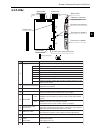
2
Connector for programmer
When using a remote monitor or remote programming function, connect
a JW-14PG programmer.
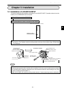
3
Connector for 10BASE5
Connect the 10BASE5 transceiver cable.
Make sure to slide the lock securely to the "lock" position.
4
Connector for 10BASE-T Connect 10BASE-T twisted-pair cable.
5
12 VDC power supply
input terminal
When 10BASE5 is used, connect a commercially available DC power
supply that is designed to supply power to transceivers. The DC power
supply must provide 12VDC 5% and 0.5 A or more.
6
Reset switch Only used by SHARP engineers. Users should not press this switch.
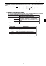
7
Switch SW2
ON
Turn ON when the shields on the 10BASE-T connectors or 10BASE5
connectors are connected to the FG (base) of the JW-50FL.
OFF
Turn OFF when the shields on the 10BASE-T connectors or 10BASE5
connectors are not connected to the FG.
- Ground the FG line on the 12 VDC connector separately.
8
Switch SW3
Specify a parameter address (in system memory) from 0 to 4.
- See page 12-4.