


4-1
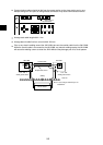
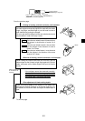
Station No. switch
Switch
1
2
3
4
5
6
7
8
9
0
UNIT
NO.
Module No. switch
Shield ground switch
1
2
3
4
5
6
7
8
9
0
1
2
3
4
5
6
7
8
9
0
Mode switch
A
B
C
D
E
F
0
1
2
3
4
5
6
7
8
9
Termination resistance
switch
Factory
setting
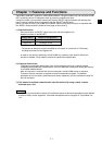
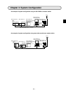
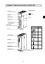
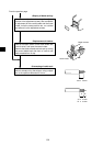
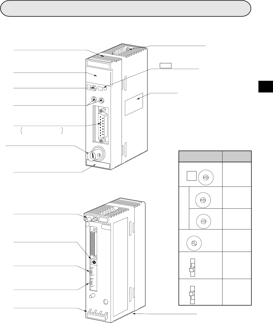
Chapter 4: Name and Function of Each Part
Ventilation hole
(Prevent temperature rise inside)
Indication lamp
(See page 12-1)
Module number switch
(See page 11-2)
Station number switch
(See page 11-3)
Support tool connection connector
Connect a support tool
and set parameters
Communication cable
connection connector
(Connect master station and slave station)
Rating plate
mark
Module retention screw
(For fixing on a rack panel)
(Applied to JW30H)
(Front view)
4
3
2
1
0
F
E
D
C
B
A
9
8
7
6
5
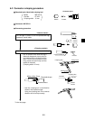
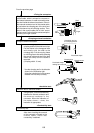
Module insertion guide
(Insert into a rack panel)
Mode switch (
(See page 11-2)
Termination resistance switch (
(See page 11-3)
Shield ground switch (
(See page 11-4)
Module retention rib
(For fixing on a rack panel)
Ventilation hole
(Prevent temperature rise inside)
(Rear view)
30Hn
ME-NET mark