


5-1
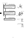
Turn "OFF" the power supply to the JW20/JW20H/JW30H.
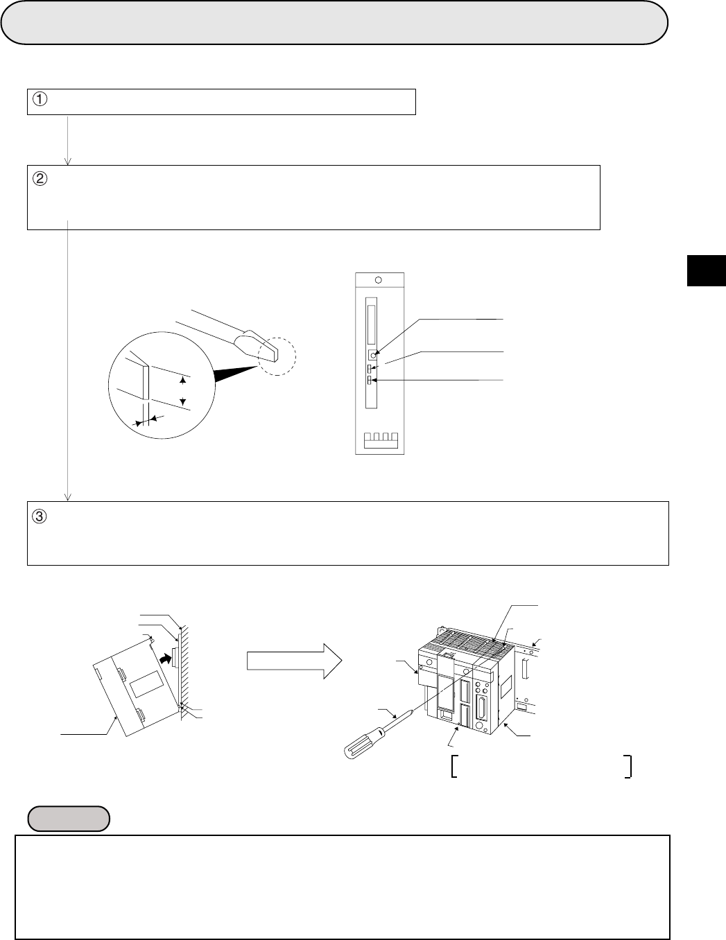
Set the mode switch, the termination resistance switch, and the shield ground switch on
the rear side of the JW-21MN.
(See page 11-2 to 11-4 for settings)
- The JW-21MN cannot be installed on the expansion rack panel.
- Number of installations of the JW-21MN on the same JW20/JW20H/JW30H basic rack panel should
be within 7 in total including other option module (including JW-21MN). Installation of more than seven
modules of the JW-21MN will not allow the JW20/JW20H/JW30H to function.
- Make sure to tighten the module retention screws securely. Looseness of the screws may cause
malfunctions.
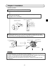
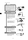
Chapter 5: Installation
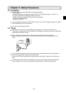
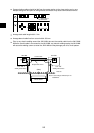
Installation procedure
Hang the module retention rib of the JW-21MN on the retention rib insertion hole of the JW20/
JW20H/JW30H's basic rack panel, and press in the JW-21MN. Then tighten the module retention
screws at the top of the JW-21MN module using a Phillips screwdriver.
Remarks
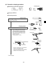
MODE
ON
OFF
LT
LG
ON
OFF
Applicable screwdriver
(Rear view of the JW-21MN)
Mode switch
Termination
resistance switch
Shield ground switch
(Installation example)
Module retention rib insertion hole
JW-21MN
Power supply
module
JW-21MN
Partition plate or control panel
Basic rack panel
Module insertion guide
Phillips
screwdriver
Basic rack panel
Module retention screw
Ventilation hole
Module retention rib