


7-2
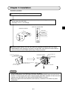
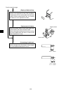
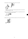
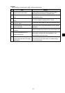
(1) Fixing of the cable
In order not to put any force on the cable and the
JW-21MN, fasten the cable to an line nearby input of
a control panel or a "T" branch point to the JW-
21MN using saddles etc.
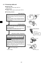
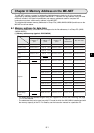
(2) Extra length of cable
Provide an extra length of the cable of 2 to 3 m
inside a control panel for easier processing of the
cable end and easier wiring when changing module
positions.
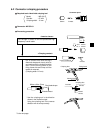
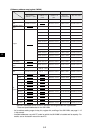
(3) Connection to the JW-21MN
The connector to the JW-21MN should be turned
right to secure locking, not merely inserted.
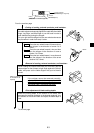
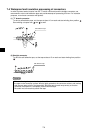
(4) Insulation cover
When the connector touches with a high voltage
section or external enclosures, communication
errors may occur. Make sure to install an insulation
cover.
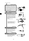
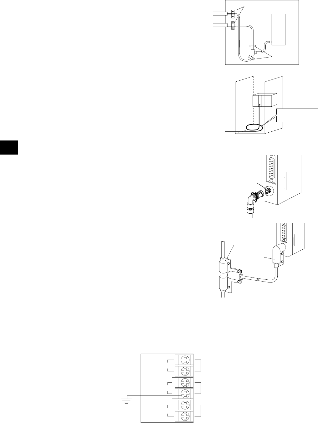
(5) Grounding of power supply module (JW-22PU/31PU)
Make sure to use a class-3 grounding to connect the GND terminal of the power supply module.
- If the power supply module is not grounded, the JW-21MN cannot conduct with the ground after
turning "ON" the shield ground switch.
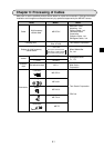
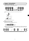
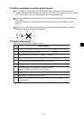
7-3 Cable wiring procedure in control panel
Saddle
Saddle
JW-21MN
Communication cable
connection connector
"L" jacket
(insulation cover)
"T" jacket
(insulation cover)
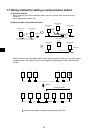
POWER
INPUT
100-120VAC
SHORT
GND
HALT
OUTPUT
100-120VAC
(24VDC)
1A
GND (ground) terminal
Halt output terminal
Class-3
grounding
Power input terminal for
85 to 132 VAC
When using a JW-31PU AC power supply module